From RF to RAID: Enabling Technologies of RF Stream-to-Disk Systems
Overview
In this white paper, learn about several fundamental technologies that are necessary for RF stream-to-disk systems.
Contents
Introduction
For as long as instruments have used digital technologies, waveform acquisition and generation size has been limited by the amount of onboard memory on the instrument – usually on the order of several hundred megabytes. However, innovations in instrument technology enable new mechanisms of waveforms storage which drastically increase waveform storage sizes. The old bottleneck in instrument-to-disk data transfer was the bus speed. In the past, this was typically slower than the acquisition rate. Today, PC-based PXI instruments have changed this paradigm completely. The combination of high-speed data buses such as PCI and PCI Express and high-speed RAID disk configurations has increased waveform storage sizes to several terabytes or more. This is known as streaming or stream-to-disk technology. We can define streaming as the following:
stream·ing [stree-ming] – verb
1. The act of transferring data to or from an instrument at a rate high enough to sustain continuous acquisition or generation.
In the following paper, we will briefly describe a few applications that benefit from stream-to-disk technology. In addition, we will provide an in-depth explanation of several technologies that enable RF stream to disk systems.
RF Stream-to-Disk Applications
While stream-to-disk technology enables a wide variety of applications, two in particular see the greatest benefits from this capability. These applications are: 1) signal intelligence / spectrum monitoring and 2) RF record and playback for receiver validation and verification.
In signal intelligence applications, instruments are required to capture RF bandwidth for long durations of time. With stream-to-disk technology, PXI systems can be used to capture up to 20 MHz of real-time bandwidth for several hours. These long records provide a rich set of data that enables easy identification of interference signals. Common types of interference signals include: “piggybacking” signals attempting to use the existing communications infrastructures; and “jamming” signals attempting to break a communications link. Both signal types are often periodic in nature. Thus, identification of interference signals requires both long duration acquisitions and joint time and frequency domain measurements such as the Gabor Spectrogram. For more information on post-analysis techniques for signal intelligence applications see: Strategies for Signal Intelligence: from Antennas to Analysis.
A second application for RF stream-to-disk systems is their use as RF record-and-playback hardware is design validation of wireless receivers. In the past, receivers were commonly tested highly elaborate with “dirty transmitter” waveforms which simulated parameters such as additive white Gaussian noise (AWGN) and multi-path channel fading. However, the complexity of producing accurate RF environment models combined has resulted in engineers using RF record and playback systems to simulate the real-world environment. Thus, simulation models can often be replaced with “perfect” simulations that have been recorded using a vector signal analyzer.
RF Stream to Disk Core Technologies
Traditional RF instruments such as vector signal generators and vector signal analyzers use standard RAM (Random Access Memory) as a mechanism for waveform storage. As a result, maximum generation and acquisition sizes for these RF instruments are typically limited to several hundred megabytes at best.
However, the combination of a high-speed data bus and RAID technology enables longer acquisition rates. Moreover, for RF signals, an RF analog front end and digital signal processing technologies enables efficient generation and acquisition of signals using superheterodyne upconversion and downconversion. A high-level system diagram of a typical system is illustrated in the figure below.
Figure 1. Several core technologies enable RF stream-to-disk.
As a result of each of these components, instrument memory can be supplemented with high-speed RAID (Random Array of Inexpensive Disks) hard drive configurations. In this scenario, data can be transferred from the instrument to hard disk at rates that exceed the rate of acquisition. Thus, the maximum waveform size is no longer limited by size of onboard memory, but by the size of available hard disk space. Using external RAID hard drive configurations, the waveform storage can be expanded to up to several terabytes of data.
Part 1: RAID Hard Drive Configurations Enables
Redundant Array of Inexpensive Disks (RAID), is a mass storage technique that uses enables the use of multiple hard disks as a mechanism increase hard disk read and write speeds. By reading and writing to or from multiple disks in parallel, the overall disk speed can be increased significantly. For RF instrument applications, RAID systems can be used as a mechanism for high-speed waveform storage.
While RAID-0 systems are typically used to maximize transfer rates, there are various RAID configurations (RAID-1 through RAID-5). Choosing a RAID configuration requires us to evaluate the tradeoff between data redundancy and data throughput.
RAID-0: Striped Set without Parity
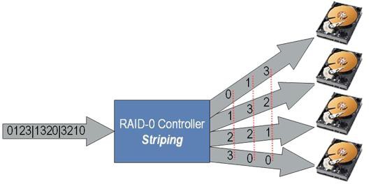
Using this configuration, data is equally divided into fragments across a number of disks. Ideally, RAID-0 systems multiply the read and write speed by the number of hard drives present in the system. RAID-0 hard drive configurations are most popular because they provide the most dramatic increase in effective disk rate. However, for long term storage, they do have disadvantages. Most notably, because there is no parity between individual disks, the entire data set is lost if only one drive fails. An illustration of a RAID-0 system is shown below.
Figure 2. RAID-0 striping
As the figure illustrates, a four-drive system is capable of improved disk speeds by sharing the read and write load across four individual drives. Moreover, because four sets of data can be written to disk simultaneously, the typical speedup for a 4-drive RAID-0 configuration is close to 4x.
RAID-1: Mirrored Data Sets
With this configuration, each data set is written as a duplicate on each hard drive in the system. The primary benefit of RAID-1 configurations is reliability, since data can be recovered as long as one drive is operational. When writing data to file, disk write speeds are actually decreased in RAID-1 configurations (compared to a single) disk because the same set of data must be written twice – though in parallel. On the other hand, disk read speeds are increased in RAID-1 configurations. Because reading from disk requires some mechanism of searching for the desired data set, this search time decreases when multiple disks can be searched in parallel.
RAID-2: Striped Data at Bit Level
In the RAID-2 configuration, disks are synchronized by the controller to spin in perfect tandem, which enables extremely high data transfer rates. This is the only original level of RAID that is not currently used. Using error correction codes, RAID-2 systems are capable of error correction if one of the drives fails. However, this system is difficult to implement because of the challenges of synchronizing multiple hard disks. Moreover, the improvements in disk speeds that result can be achieved in more practical ways. As a result, RAID-2 is not typically used in RF stream-to-disk systems.
RAID-3 and RAID-4: Striped Set with Dedicated Parity
Both RAID-3 and RAID-4 systems are similar in function to RAID-0, but with one distinct difference. In these systems, a dedicated hard-drive is used for bit parity to increase fault tolerance. If one drive fails, data can typically be recovered as long as the parity drive does not fail. Thus, RAID-3 and RAID-4 systems are able to achieve the increased disk speeds utilizing multiple disks in parallel while maintaining lower risk of losing data to disk failure. The only distinction between the two systems is that RAID-3 uses bit-level parity and RAID-4 uses block-level parity.
RAID-5: Striped Set with Distributed Parity
This system is similar to RAID 3 and RAID 4, but with one distinction. In RAID-5 systems, parity is rotated between all disks in the system. Thus, the entire data set can be reconstructed even if one disk fails. Overall the performance increase is slightly less than with RAID-0 (no parity), but RAID-5 systems are much more fault-tolerant. As a result, RAID-5 is provides both a high-performance and a high-redundancy mechanism for waveform storage.
Choosing the Best RAID Configuration
While the discussion above provides a high-level overview of tradeoffs when configuring a RAID system, this level of technical detail is typically transparent to the user. Typically, a RAID system is configured once and most RAID drivers offer RAID-0 or RAID-5 options. After configuration, the operating system enables the user to use the entire RAID system as a single hard drive. Once configured as a logical drive, the RAID driver can be accessed using file read and write commands in LabVIEW. Thus, when configuring the RAID system (upon installation), RAID-0 or RAID-5 should be chosen according to the requirements for throughput and redundancy. As an example, typical PXI Express RAID-0 configurations are able to achieve 600+ MB/s of sustained disk read and write speeds.
Part 2: High-Speed Data Bus: PXI and PXI Express
The second key technology required for RF streaming applications is a high-speed data bus. With traditional RF instrumentation, data busses between the PC and instrument were typically GPIB, USB, or Ethernet based. Because traditional busses offer on the order of 2-10 MB/s of sustained throughput, streaming data to a PC was impractical because the bus speed was a severe bottleneck for data.
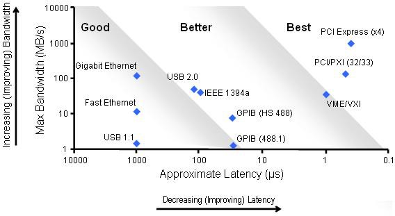
With today’s PXI (PCI Extensions for Instrumentation) and PXI Express RF instruments, the paradigm for data transfer has changed. Both PXI and PXIe instruments feature high-speed low-latency data busses which enable streaming data from the instrument’s onboard memory to hard disk at the maximum data rate of the instrument. In the figure below, we compare the throughput and latency of PXI and PXI express.
Figure 3. Bandwidth vs. latency for data buses
The Compact PCI Bus
PXI instruments are based on the compact PCI bus commonly used in personal computers. The PCI is a parallel bus with slightly varying implementations. In PXI instruments, the PCI bus is 32-bits wide operates with a 33 MHz clock. The theoretical maximum bandwidth is 132 MB/s with typical latencies less than 1µs. In practical applications, LabVIEW PXI instrument drivers use direct memory access (DMA) and optimized packet transfers to achieve sustained data throughput on the order of 110 – 120 MB/s, depending on the specific instrument.
Note that because the PCI bus is a “parallel bus”, all of the devices on the bus share the total bandwidth. Thus, as additional instruments requiring sustained bus bandwidth are added, the available bandwidth to each instrument decreases.
The PCI Express Bus
PCI Express, is an evolution of the PCI bus and is used in PXI Express instruments. It maintains complete software compatibility with PCI, but utilizes a high-speed serial bus instead. With PCI express, data is send through differential signal pairs called lanes. Each lane offers 250 MB/s (theoretical) of bandwidth per direction per lane. Multiple lanes can be grouped together to form links with typical link widths of x1 (pronounced "by one"), x4, x8, and x16. A x16 link provides 4 GB/s bandwidth per direction.
Moreover, unlike PCI, which shares bandwidth with all devices on the bus, each PCI Express device receives dedicated bandwidth. The PXI Express standard supports up to 6 GB/s of total system bandwidth (controller to backplane) and up to 2 GB/s (x8) of dedicated bandwidth per slot (backplane to module). As an example, consider using PXI a vector signal generator to generate an RF signal at 40 MS/s. At this sample rate, the bus would be required to sustain 160 MB/s of maximum throughput (4 bytes per complex sample). At this data rate, the instrument’s maximum sample rate does not even approach the maximum bandwidth of the bus.
Bus Speeds Enable New Virtual Instrument Architectures
A high-speed data bus such as PXI and PXI Express enables high-bandwidth data transfer form an instrument to disk. Because the speed is often greater than the data rate of the instrument, RAID hard drive configurations can be used to supplement the onboard memory of the instrument. Thus, a typical RF instrument with 512 MB of onboard memory is now capable of continuous acquisition for up to several terabytes of data. As an example, a PXI RF vector signal analyze connected to a 2 TB raid drive can continuously acquire 20 MHz of RF bandwidth for up to 5+ hours. With today’s PXI instrumentation, the combination of a high-speed bus and high-bandwidth disk configuration effectively expands the onboard memory of PXI RF instruments from megabytes to terabytes.
Part 3: Digital Signal Processing Techniques
For instruments such as high-speed digitizers and arbitrary waveform generators, stream-to-disk systems can be implemented merely by adding an analog front end to a high-speed data bus. However, RF instruments can require additional digital signal processing techniques.
In general, RF instruments can be implementing using one of two basic methods for upconversion and downconversion. These two methods, homodyne (also called direct) and superheterodyne (IF-based) provide various tradeoffs according to the specific application. For example, spectral monitoring and record and playback applications require heterodyne downconversion because of the images that can result from direct downconversion. As another example, generation of RF signals produces additional challenges. Because digital-to-analog converters produce images in the frequency domain at multiples of the sample rate, it is important to sample base baseband signals at several times the signal bandwidth.
In both cases, the challenges of both homodyne and superheterodyne upconversion and downconversion require digital signal processing techniques to reduce the data rate without compromising the analog signal. For RF stream-to-disk applications, the use of DSP techniques enables wider bandwidth of sustained acquisitions.
For instance, continuous acquisition of 20 MHz of RF signal bandwidth would requires sample rate of at 100 MS/s when using an IF carrier of 25 MHz. In terms of data, this translated to 200 MB/s. However, using digital downconversion, we can acquire this data as a baseband I and Q signal instead of IF. With a baseband sample of 25 MS/s, our data rate has been reduced to 100 MB/s (2 bytes for I, 2 bytes for Q). Thus, digital signal processing techniques reduce required data rates for instruments using superheterodyne upconversion and downconversion. As ar result, waveform storage mediums such as RAID systems can be more effectively utilized.
Basics of Digital Upconversion
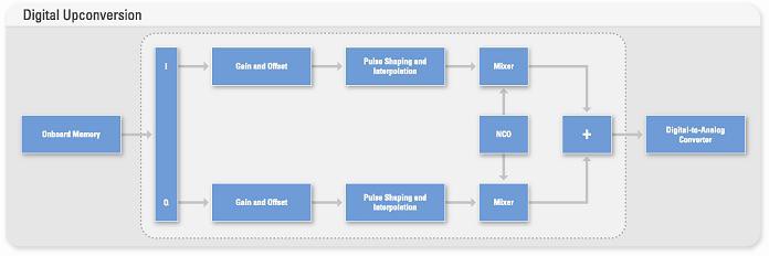
Digital upconversion enables translation of baseband I and Q signals to an intermediate frequency without introducing phase, gain, or offset errors. A typical block diagram of digital upconversion is represented below.
Figure 4. Block diagram of digital upconversion.
As the block diagram illustrates, digital upconversion requires interpolation of a baseband waveform to enable mixing with a digital in-phase or quadrature-phase carrier. Moreover, digital signal processing also enables application of pulse-shaping interpolation filters (raised cosine, root-raised cosine, etc.) without increasing the data rate on the bus.
Basics of Digital Downconversion
Vector signal analyzers use a similar onboard signal processing technique to digitally downconvert IF signals to baseband. Digital downconversion enables the advantages of oversampling an IF signal while eliminating the needless data that is acquired. Like digital upconversion, digital downconversion uses a digital numerically controlled oscillator (NCO) to produce digital in-phase and quadrature-phase components of a digital IF carrier. The resulting baseband I and Q signals can than be decimated to the desired symbol rate.
Note that decimation of baseband signals is not as simple as just removing unwanted samples. Because aliasing can occur when samples are merely dropped, a combination of low-pass filtering and removing samples must occur to preserve the signal integrity.
Onboard Signal Processing (OSP) on RF Instruments
National Instruments offers RF instruments with onboard signal processing to perform digital upconversion and digital downconversion of baseband and IF signals. This functionality is implemented in hardware on a field-programmable gate array (FPGA). The FPGA enables real-time digital upconversion and downconversion for signals requiring up to 40 MHz of bandwidth. Because digital signal processing is performed in real-time with the DUC and DDC, baseband waveforms can be streamed to and from the hard disk.
Part 4: RF Analog Front End
The final stage in an RF stream-to-disk system is the RF analog front end. NI vector signal generators and analyzers are able to stream up to 20 MHz of RF bandwidth to and from disk at frequencies of up to 2.7 GHz. Both of these instruments utilize a superheterodyne approach for frequency translation to RF.
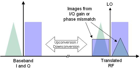
In many ways, the RF analog front end is one of the simplest technologies used in RF stream-to-disk systems. However, it should be noted that there are trade-off that must be considered when choosing direct vs. superheterodyne approach to frequency translated. In general, direct upconversion provides the user with greater phase noise and dynamic range performance. However, this the direct approach to upconversion and downconversion does introduce images in the frequency domain. This is illustrated in the figure below:
Figure 5. Direct upconversion and downconversion is prone unwanted images
These images are caused by gain imbalance or phase mismatch between analog I and Q signals.
When using a direct conversion for RF stream to disk systems, users must configure a customer direct upconverter or downconverter to be use with a high-speed digitizer and arbitrary waveform generator. Moreover, NI baseband instruments use a patent-pending technology called NI-TClk to minimize synchronization errors.
For spectrum monitoring applications, identification of low-level peaks in the frequency domain is an essential part of making accurate measurements. Thus, for these applications, it is important to use a vector signal analyzer that implements superheterodyne downconversion. Using the superheterodyne approach, downconversion from IF to baseband is accomplished digitally. Thus, the images introduced through the direct conversion technique are avoided.
Part 5: Using LabVIEW’s Multithreaded Environment
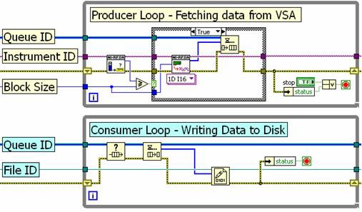
The final enabling technology for RF stream-to-disk applications is a multi-threaded programming language such as LabVIEW. In LabVIEW, parallel operations are automatically assigned to processor threads by the LabVIEW complier. Thus, RF stream-to-disk programs can be optimized simply by using parallel programming practices. The recommended programming approach is the producer-consumer loop structure, which is shown in the figure below.
Figure 6. Producer-consumer loop architecture using the queue structure
In the example above, the top loop (producer) acquires baseband I and Q data from a vector signal analyzer and passes it to a queue structure (a LabVIEW FIFO). The queue structure is able to pass data between multiple loops in LabVIEW, enabling the bottom loop (consumer) to write the data to disk. The producer-consumer loop structure delivers the best performance for stream-to-disk applications because the producer loop can continue to acquire data while the consumer loop is writing data to disk.
LabVIEW provides an ideal programming environment for RF stream-to-disk applications, because of its inherently parallel and multi-threaded nature. This can result in even greater performance on multi-core processors, where parallel processes can be assigned to individual cores.
Typical RF Streaming Benchmarks
The typical stream-to-disk system includes a PXI vector signal analyzer, PXI chassis and controller, and a RAID hard disk. There are several hard disk options for RF stream-to-disk systems. With PXI-based systems, the limiting factor is the PCI bus, which can support on the order of 110 MB/s of sustained throughput. Note that NI has made significant optimizations to the NI-RFSA and NI-RFSG drivers to support streaming applications. Thus, using a third-party PXI vector signal analyzer does not guarantee the same streaming rates.
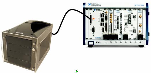
The recommended architecture is to use an external hard drive array via an ExpressCard External SATA (eSATA) module. The ExpressCard module includes an integrated RAID-0 controller and uses a x1 PCI Express link to sustain streaming rates to and from the hard drive array at over 110 MB/s. The hard drive array supports multiple terabytes of storage capacity, which enables continuous streaming at full rate for several hours. A typical system is illustrated in the figure below.
Figure 7. Typical system setup for RF stream-to-disk
Using the hard drive configuration shown above, we are able to stream RF signals for but input and output at the full instantaneous bandwidth of the instruments (20 MHz). Because RF signals are acquired as complex data, each I and Q sample require 2 bytes each for a total of 4 bytes per sample. The data conversion is as follows:
Data Rate = Sample Rate x 4 bytes/sample
Using the equation above, we can calculate the total RF streaming bandwidth and total acquisition time using a 2 terabyte RAID hard drive configuration from Addonics. The total RF bandwidth and record length is shown as a function of IQ sample rate in the table below:
| Sample Rate | RF Bandwidth | Hard Drive Size | Record Length |
|---|---|---|---|
8.33 MS/s (IQ) | 6.66 MHz | 2 Terabytes | 16+ Hours |
10 MS/s (IQ) | 8 MHz | 2 Terabytes | 13+ Hours |
12.5 MS/s (IQ) | 10 MHz | 2 Terabytes | 11+ Hours |
16.66 MS/s (IQ) | 13.33 MHz | 2 Terabytes | 8+ Hours |
25 MS/s (IQ) | 20 MHz | 2 Terabytes | 5+ Hours |
Figure 8. Typical benchmarks for RF streaming acquisition rates and length
The streaming rates shown above apply to both generation and acquisition. However, it should be noted that use of PXI express instruments enables even higher streaming rates than are shown in the figure above. Using PXI express instruments, multiple channels can be streamed simultaneously for up to 600 MB/s of total data throughput.
Conclusion
RF stream-to-disk technology requires an advanced set of core technologies that are only available in the PXI and PXI express platform. The combination of RAID hard disk technology, digital signal processing techniques, a high speed data bus, an RF analog front end, and the high-performance LabVIEW programming language are all necessary enable RF stream to disk systems. In addition, the evolution of RF stream-to-disk systems has enabled a world of new applications. Because stream-to-disk systems dramatically increase RF acquisition sizes, engineers can use these systems for continuous generation or acquisition in applications such as signal intelligence, wireless receiver validation, communications packet sniffing, and many others.
Related Resources
For more information on RF stream-to-disk systems in PXI, please visit one of the links below:

