Addressing DC Biasing Challenges for Modern Imaging Detectors
Overview
Modern Focal Plane Array (FPA) Imaging Detectors are simultaneously high resolution, high sensitivity, and high speed. The combination of advanced requirements often drives the need for low-noise and highly precise DC biasing for the FPA and the read-out IC (ROIC). In this white paper, you will learn how the NI modular source measure unit technology meets the needs of these advanced systems with customizable channel count, precise accuracy, configurable impedance loading, and advanced timing features.
Contents
- Common Imaging Detector Systems Architecture
- Focal Plane Array Detector Biasing Requirements
- Summary
Infrared imaging technology is a critical capability for intelligence, surveillance, and reconnaissance (ISR) missions and many non-military operations like search, rescue, and environmental monitoring. Advanced EO/IR focal plane array (FPA) imaging systems are used across all operational domains: sea, air, space, and land. As such, each domain can come with unique design requirements resulting in a wide range of system implementations. Advancement in materials used in FPA detectors has resulted in systems that are high resolution, highly sensitive, and may have high frame rates. While there is a desire to operate at ambient temperatures, the most sensitive FPA imaging detectors are cryogenically cooled and operate at very low temperatures to meet performance requirements. The combination of both high resolution and high sensitivity presents unique challenges for testing the DC biasing and the high-speed data interfaces on these systems. In this white paper, we will address the challenge of testing highly sensitive FPAs when an accurate bias voltage is required. We’ll also share several experiments and examples of using NI modular instruments for testing applications.
Common Imaging Detector Systems Architecture
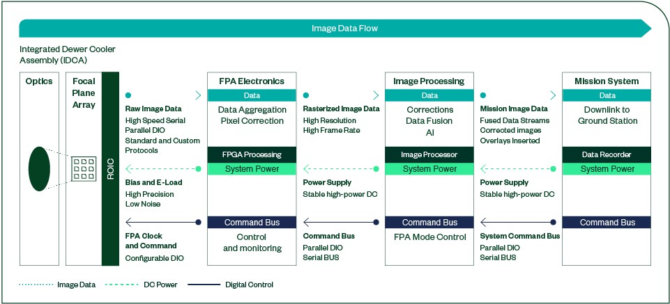
Figure 1: Common Imaging Detector System Architecture
Modern focal plane arrays are often customized to meet the unique requirements of a specific application; however, most systems share a common overall system architecture as shown in Figure 1. The FPA detector on the left has three main interfaces for data, bias, and control. The data interface, shown above as the top path, can be a high-speed data bus or an analog interface to offload image data from the read-out-IC (ROIC). The FPA is powered and biased from a range of power supply lines, which are represented by the center path on the diagram. These lines can have nonstandard voltage and loading requirements depending on the technology of the FPA device. Additionally, the FPA has a clocking and command interface to control the device during normal and testing operation, as indicated in the bottom path in the figure. The data, bias, and control interfaces often cascade through subsystems or circuit card assemblies (CCAs). The FPA electronics, sometimes called the “close-in-electronics,” are responsible for controlling the FPA, supplying the bias, and consuming raw frame data for correction and front-end processing. Subsystems are typically developed in parallel and the teams building the FPA device and the FPA electronics often must test their unit’s interfaces before the other team’s unit is ready which puts a challenge to the FPA test engineer to emulate the voltage performance of a subsystem before it is available. The unique requirements of DC bias performance testing and a proposed solution based on NI modular PXI Source Measurement Units (SMUs) are addressed in the following sections.
Focal Plane Array Detector Biasing Requirements
FPA power requirements can be challenging depending on the high-performance materials used to deliver optimum performance for the given domain and mission. The need for high density, extremely low noise power supplies with complex turn on sequences, over voltage protection (OVP), and predictable over current protection (OCP) makes biasing focal planes challenging. Making a second “reverse” solution is also necessary to provide a load to the electronics delivering the power and bias. Here is a list of common requirements for modern FPA detector power and biasing test equipment:
Tester Signal Requirements
- Many Independent bias supplies per detector
- Power envelope, less than 6 V (typical) with up to 2,000 mA per bias
- Up to two 3 0V, <10 mA biases
- Wideband low-noise performance
- Excellent overcurrent protection and overvoltage protection
- Precise on/off sequencing
- Sink and source capabilities for reuse across the development cycle
Tester Best Practice Requirements
- Convenient connectivity
- Flexibility and reusability
- Robust and sustainable software stack
- Standard-compliant calibration
- Long lifecycle components
- Simple integration into tester
- Low cost
Common Approaches to Biasing Test Approaches: Custom vs COTS
Traditional FPA DC test solutions are often developed in one of two ways: fully custom hardware delivering near “flight-like” conditions, or traditional commercial-off-the-shelf (COTS) rack mount power supplies with load drawers or E-loads that more coarsely simulate system conditions.
Custom Test Hardware
While architectures for FPAs are often similar, a particular FPA has biasing requirements that are specific to the design of the device such as custom overvoltage-protection (OVP), overcurrent-protection (OCP), good channel density, and exact channel timing and sequencing. Figure 2 shows an example of a representative custom solution.
However, these solutions are typically saddled with significant nonrecurring engineering (NRE) costs with funding often tied to a specific program. On top of the added NRE and ensuing schedule risk, custom solutions also require a long-term internal support and funding commitment as a team of qualified engineers must be retained, legacy software and operating system updates must be handled, and hardware obsolescence must be managed.
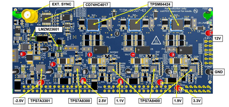
Figure 2: Example Custom PCB for FPA Biasing and Interfacing
Traditional COTS Test Solution
When the test strategy is built on traditional COTS rack-mount power supplies, this approach can offer quality noise performance, wide power envelopes, low lead times, and a much more sustainable solution. However, this approach often comes at a high capital cost and increased test bench real estate and can struggle to meet many of the “flight-like” test needs met with a custom solution. Deterministic, multichannel sequencing is typically not supported; and while OCP/OVP cutoffs are robust, their response time is often relatively slow, which can lead to large power dissipations into the devices being tested. Power supplies must also be paired with an E-load solution providing loading/testing bias supply boards, which roughly doubles the solution cost.
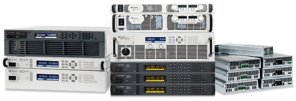
Figure 3: Standard Box Instrument DC Power Supplies
Modular COTS—The Best of Both Worlds
NI's modular COTS approach solves the technical and operational challenges of proper FPA bias testing. The NI solutions include high-performance SMUs built on the PCIe Extension for Instrumentation (PXIe) modular instrumentation platform standard.
NI PXI Express SMUs bring the benefits of both custom and COTs to FPA test engineers. The high-performance power supplies are COTS, which eliminates the need for customized development and saves NRE. They also have specific features to allow for flight-like noise and impedance performance common in many custom-built biasing test solutions. PXI Express is an interoperable modular standard for instrumentation allowing you to scale the number of FPA biasing channels to meet unique system requirements without extensive customization.
To remove the need for E-loads, many NI SMUs include SourceAdapt® technology, which is a patented capability allowing you to digitally tune the impedance of your bias channel without external E-loads or load drawers. Figure 4 shows an example how SourceAdapt tuning can avoid voltage overshoot and power your FPA in a more flight like way, without the custom hardware. A predictable matched power supply will lead to less tester related anomalies, improving the confidence of your end customer and lead to fewer false failures.
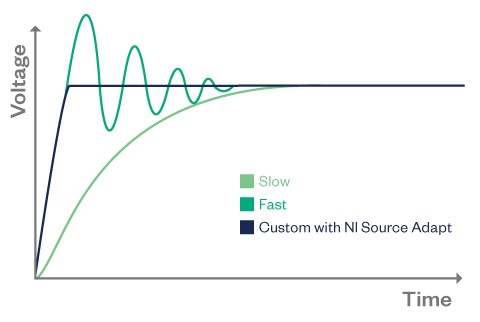
Figure 4: NI Source Adapt Technology for SMUs
Modular COTS Configuration Example
In the following sections, we will walk through several example test configurations and performance examples based on the NI PXIe-4147 and PXIe-4139 and explore how these two modular SMUs meet specific performance metrics required by high performance FPAs today. Refer to Table 1 for product specifications.
| PXIe-4147 | PXIe-4139 | |
|---|---|---|
| Channels | 4 | 1 |
| Maximum Voltage | 8 | 60 |
| Max Current | 3,000 mA | 3,000 mA |
| W per Channel | 24 | 40 |
| W per Card | 40 | 40 |
| Quadrants | 4 | 4 |
| Sensitivity | 100 fA | 100 fA |
| Update Rate | 200 kSa/s | 200 kSa/s |
Table 1: NI PXI Express SMU Product Specifications
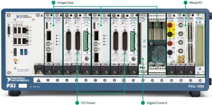
Figure 5: Typical FPA Interface Test Solution in PXI Express
Figure 5 shows an example configuration using PXI Express modules that control interfaces common in FPA systems. Image data often connects to or from storage through a high-speed serial data interface module. Power and bias are controlled through various NI DC power supplies or a source-measure-units capable of providing power, measuring voltage/current, and adjusting load impedance. The system shown in Figure 5 is configured to support two parallel FPA digital and DC interfaces.
Benchmarking Overvoltage protection, Overcurrent Protection and Noise performance
When testing FPAs three common performance metrics are important, overvoltage protection (OVP), overcurrent protection (OCP), and noise performance integrated over a specific frequency band. Below are several test benchmarks along with their results, which are representative of common FPAs tests using the NI PXIe-4147 and PXIe-4139.
Measuring power supply noise performance
The most common method for testing DC bias noise performance is to measure noise across a specified frequency band, as a peak-to-peak, or RMS noise measurement in volts. Noise performance is dependent on device range, setpoint, and SourceAdapt transient settings, so we have taken representative data of some typical use-cases which you can see below in table 2.
| Frequency Band | Target Aggregate Noise |
|---|---|
| 100 Hz to 10 kHz | <20 µVrms |
| 10 kHz to 100 kHz | <60 µVrms |
| 100 kHz to 10 MHz | <600 µVrms |
Table 2: Typical Bias Noise Requirements
Warranted noise performance for the PXIe-4147 and PXIe-4139 is specified for close-in peak-to-peak noise from 0.1 Hz to 10 Hz as well as wide-band peak-to-peak noise from 10 Hz to 20 MHz. While these are the published warranted specifications, many FPAs require noise performance to be measured more granularly across the several frequency bands listed below. For our benchmark below we show results common for these configurations.
Common FPA Biasing Measure Noise Performance Frequency Bands:
- 100 Hz to 1 kHz
- 1 kHz to 10 kHz
- 10 kHz to 100 kHz
- 100 kHz to 1 MHz
- 1 MHz to 10 MHz
Overcurrent and overvoltage protection performance
The class of FPAs in consideration tend to be quite sensitive and expensive devices that require careful consideration to ensure the test setup does not damage the device under test when placed in certain operating conditions. Even small inadvertent energy discharges can cause tens (or hundreds) of thousands of dollars of damage, so overcurrent and overvoltage protection is critical to shield the device in the event of a short circuit or similar event. NI SMUs have several mechanisms for overvoltage and overcurrent protection that have different implications in terms of response rate and behavior.
Overcurrent and Overvoltage protection standard limits
In a default operating mode, the NI SMUs are controlled by two primary values: The setpoint for the control mode and the compliance limit. For voltage bias testing, the SMU is typically configured with a voltage setpoint and a current limit. In the typical operating mode, the SMU will bring its voltage up to the setpoint if the current limit is not exceeded. In the case where there is an event such as a short circuit and the current limit is reached, the device will go into “compliance” mode and limit the voltage while keeping the current at its limit. The timescale for this event is dependent on the SourceAdapt settings of the SMU. This compliance mode is accomplished in hardware on the device, which is both deterministic and fast.
Overcurrent and Overvoltage protection test software limits and behavior
As an additional layer on top of the hardware-based control, the SMU also reports values back to the host computer using the NI-DCPower API. This scenario allows users to make additional decisions at a software layer, which gives additional flexibility in terms of decision making. The benefit is that there are many more complex behaviors that can be achieved such as triggering a complex shutdown/power-down sequence, doing a hard disconnect of the device, or changing limits on the fly.
The downside to this software-based approach is that it does involve a software layer, which can be longer and nondeterministic in terms of timing and can have rare failure modes such as a computer system lockup. Because of this constraint, software-based OCP should be seen as a powerful but secondary option that should not be solely relied upon for device protection.
Overcurrent and Overvoltage protection cutoff feature
NI-DCPower includes a feature on the PXIe-4139 called “Output Cutoff.” The Output Cutoff function independently monitors SMU output measurement and initiates a fast disconnect when any of these measurements or slew rates exceeds a programmed threshold. Rather than putting the device into compliance—which holds the current limit—the system will open relays, bringing the voltage and current to zero in a hardware-deterministic manner.
Overcurrent and Overvoltage protection hardware test setup
To test our OCP/OVP performance, we emulate a short circuit scenario, which is one of the most demanding and risky in terms of energy dissipation into the device. We use a high-speed digitizer to measure voltage and current to see transient performance, shutdown time, and energy dissipation. For this test we use a 3.3V rail across a 5.6 Ω resistive load (597 mA nominal), with a compliance limit of 700 mA, then fault the system to ground. For transient settings, we set SourceAdapt to “fast” for best settling time. Sense lines are used to compensate for lead wire and shunt resistance. A short-circuit fault is inserted at a predetermined time using a PXIe-2514 PXI Signal Insertion Switch Module to emulate a short circuit condition. The test system setup is shown in Figure 6.
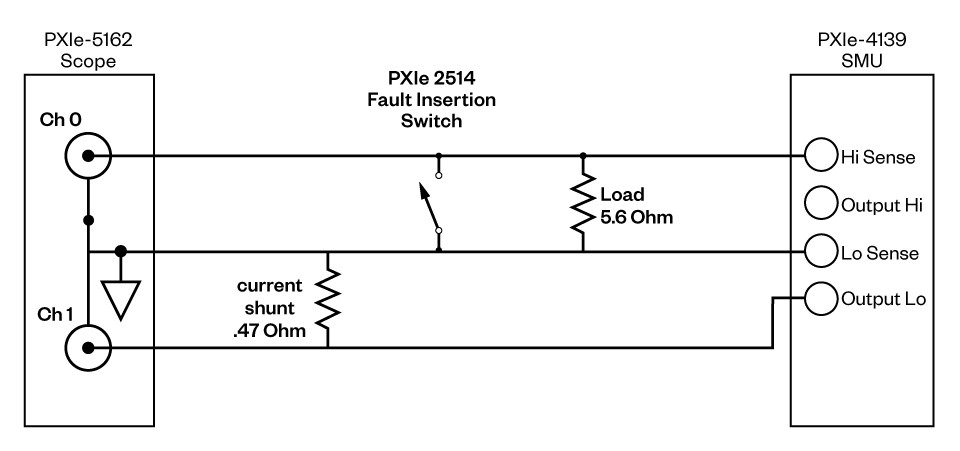
Figure 6: Overcurrent and Overvoltage Protection Test Setup
Overcurrent protection test results
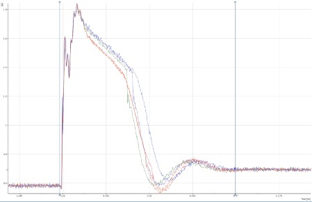

Figure 7: Overcurrent Protection Test: Voltage Graph (Left), Current Graph (Right)
As can be seen on the voltage graph in Figure 7, voltage was set at 3.3 V with a 700 ma current limit. At approximately 0.25 ms on the graph, the PXIe-2514 fault insertion switch was closed. You can see the current rapidly rise to a transient peak of 1800 mA then settle to the 700 mA compliance limit within 18 µS, for a total energy dissipation into the device of only 13 nanojoules. From here it held at 700 mA compliance as voltage drove to near zero.
Overvoltage protection with ‘Output Cutoff’ test results

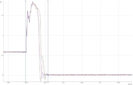
Figure 8: Overcurrent Protection Test with ‘Output Cutoff’: Voltage Graph (Left), Current Graph (Right)
In this test the voltage was again set to 3.3 volts. When the fault insertion switch is closed, the currently rapidly rises. As you can see in Figure 8, the current rapidly rises to a transient 1800 ma and quickly falls as full cutoff is initiated. The initial voltage drop happens over <1 µS with full cutoff.
Hardware timed sequencing
On some FPAs several power supplies and biases may be required. In many systems, DC power must be applied in a specific order and timed precisely. One powerful biasing feature of NI SMUs is their ability to execute multichannel hardware-timed sequences. This feature allows users to do full flight-like turn-on sequences with hardware deterministic timing, allowing for more thorough test of device performance and DUT firmware.
The NI-DCPower API is extremely powerful for creating complex sourcing and measurement sequences across multiple devices, enabled by trigger sharing across the PXI Express backplane.
Electronic Loading (E-Load) with NI SMUs
Both the PXIe-4139 and PXIe-4147 are true 4-quadrant source measurement units allowing them to act as both a bias supply as well as a flexible e-load to test a bias supply. This architecture enables a single unit to have many different use-cases such as using a PXI Express system as a full focal plane array emulator including bias loading, test system self-checkout, complex bias faulting emulation, and more.
To operate as an E-load, simply change the voltage set-point to zero, then use the current limit to define the nominal current setpoint you wish to drive. When the bias supply turns on, the SMU will attempt to load the system down to zero volts. The current will then increase to the compliance limit setpoint, at which point there will be a constant current draw as the voltage rises to the rail voltage.
Summary
Using NI’s PXI Express SMUs in a modular COTS solution meets the demands of modern imaging detector system focal plane array bias testing. Modern FPAs are both high speed and highly sensitive, requiring customized biasing to meet the stringent noise requirements while also protecting the high-cost device under test from damage by the test set. The NI PXI Express SMU solution for FPA bias is the best of both worlds with features like a custom designed test bias circuit with the noise performance of a high-end box instrument SMUs. The NI solution allows for more flexible, flight like, and sustainable testing of biasing versus standard COTS based solutions. These techniques can be scaled across devices, projects, and programs, helping to dramatically lower the overall cost of test and remove the time pressure often placed on validation and production test teams.
An NI Partner is a business entity independent from NI and has no agency, partnership, or joint-venture relationship with NI.