EV Powertrain Testing Challenges and Solutions
Overview
As the electrification of the automobile continues to accelerate, automotive engineers need to address new testing challenges for Battery Electric Vehicles (BEV) powertrains that did not exist previously with traditional powertrains.
Several testbed approaches exist for supplying electrical power controls. Here, we discuss these approaches and the advantages of using next-generation battery emulators from NI for testing new vehicle propulsion subsystems.
Contents
- What Is an Electric Vehicle (EV) Powertrain?
- New Challenges in Testing BEV Powertrains
- Common Test Setups: Dynamometers, the DC Bus, and Using Modern Battery Emulation
- Changing Power and Voltage Levels in Modern BEV Powertrain
- The RINT Model: Accurately Simulating Battery Characteristics
- Flexible Solutions from NI
- Summary
- Next steps
What Is an Electric Vehicle (EV) Powertrain?
Initially, an EV powertrain looked fairly similar to a traditional propulsion system; it had an engine (motor), transmission, fuel source (gasoline), and mechanical frame. More recent developments include replacing the internal combustion engine (ICE) with one or more electric motors, using new forms of transmissions and torque control, as well as using improved energy storage (batteries) to act as the fuel source.
All new powertrain components—including the motor, transmission, and frame—are rigorously tested under harsh conditions to ensure high reliability.
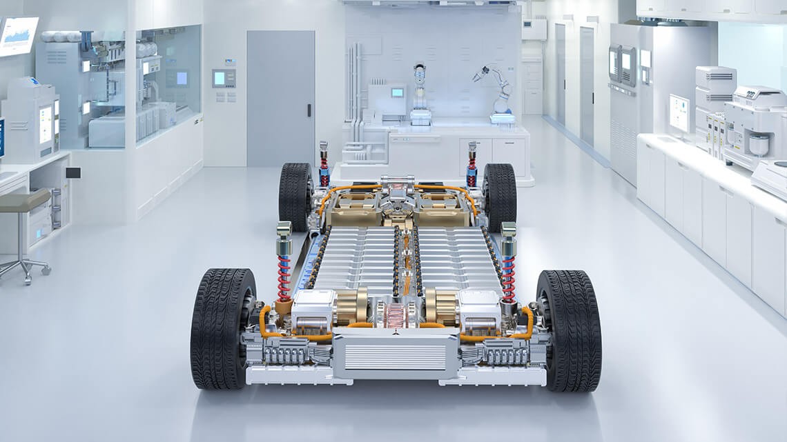
Figure 1. A Modern EV Chassis and Powertrain; Image Courtesy of Lucid Motors
New Challenges in Testing BEV Powertrains
Modern propulsion system architectures are fundamentally different and present new challenges and different risks. EV powertrains necessitate different safety considerations when compared to traditional propulsion systems.
In normal operation, traditional combustion-based powertrains require petroleum-based fuels and emit toxic fumes, both of which must be carefully controlled. By comparison, an EV powertrain has no toxic elements or emissions under normal operation but does require additional safety considerations such as high-voltage training, fixturing, and handling. Additionally, using a real battery to test the motors and mechanical systems introduces some risk of failure: a failed device could release toxic gases and caustic, corrosive fluids. It could also vent exothermically, causing smoke, fire, or an explosion.
Simply put, using a battery emulator to replace the energy storage component to mitigate these risks makes more sense. This approach improves safety, reduces test time, and provides more repeatable results.
Common Test Setups: Dynamometers, the DC Bus, and Using Modern Battery Emulation
When testing components such as sensors, transmissions, or other mechanical devices, it is common to have a test stand (testbed) with a drive motor. With this setup, you can simulate the mechanical power of the motor and/or engine and a second drive motor to simulate the mechanical loading and/or inertia of the wheels.
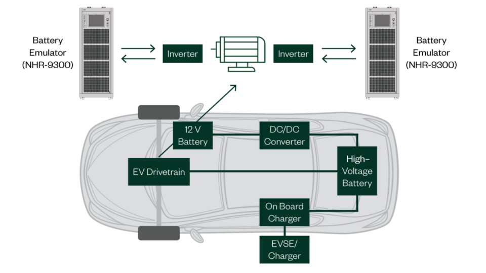
Figure 2. EV Block Diagram
When testing a full skateboard, the drive motor is included in the skateboard, requiring only a secondary motor to simulate the wheels. This second configuration is often referred to as a dynamometer, or “dyno” for short. Dynos have been used for many years to test traditional ICE vehicles.
Similarly, early EV powertrains with unidirectional power flows made it possible to use a traditional power supply. The traditional power supply could act like a battery, and you could use a traditional dyno to absorb the mechanical power generated by loading the secondary drive motor.
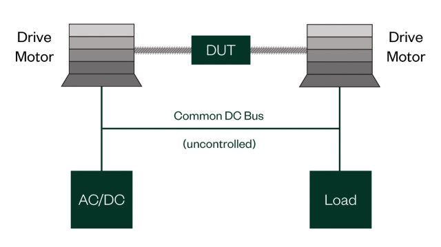
Figure 3. Common DC Bus
These early EV powertrain testing approaches quickly evolved to a common DC bus topology as shown in Figure 3. This topology attempts to capture and reuse electrical power rather than dissipating it as heat (waste). Since it is based on one or more unidirectional devices, any failure or performance limitation, such as UUT or another device, breaks the entire test setup.
Moreover, back-EMF during ramp-down or simulated engine braking can result in device damage. Finally, without isolation between the input and output, noise, harmonics, or other instabilities can affect the DC bus as well as the output or input respectively. All these factors can easily skew test results and create false powertrain conditions.
Unlike the traditional method previously described, modern battery emulation from NI provides a unique bidirectional solution that better simulates real-world conditions for energy storage in a battery and for wheel power. As shown in Figure 4, this bidirectional approach provides isolation between the input and output, eliminating single points of failure in the test setup, and automatically accepting any back-EMF generated by the UUT.
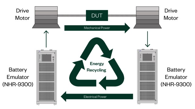
Figure 4. Powertrain Battery Simulation
Compared to the common DC bus in Figure 3, the separate input and output paths of Figure 4 remove uncertainty from the test and allow test engineers to analyze performance parameters with confidence. This approach is especially important for regenerative braking, engine inertia energy capture, and other situations requiring short bursts of power flow in either direction.
Changing Power and Voltage Levels in Modern BEV Powertrain
Power and voltage levels are transitioning from a traditional 300/400 VDC level toward 800/1000 VDC. Higher voltages permit faster charging and increase power transfer while reducing vehicle weight.
For example, in 2019 most available BEVS were similar to Tesla’s Model 3 and GM’s Chevy Bolt, with a nominal voltage of ~350 VDC, whereas Porsche announced the Taycan architecture utilizing a higher 800 VDC battery system. This higher voltage allows nearly three times the additional power to be transferred for the same wire size. Porsche demonstrated this with an IONITY system charging at 350 kW, which is nearly three times the 120 kW available through other “fast” supercharging networks.
It is expected that both 800 V and 350 V vehicles will charge at an electric-only refueling station the same way gasoline and diesel cars do today.
Engineers should keep this dual-voltage reality in mind when specifying the power requirements since many of the high-power test systems are only designed for a single range. Selecting a system that can provide both traditional and high-voltage levels ensures the right equipment is available for current and future needs. It is equally important that a battery emulation system reacts with a quick voltage response to changes in current or power draw to accurately simulate the electrical storage system (battery).
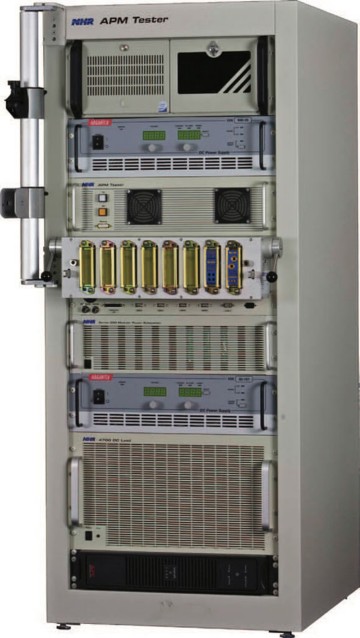
Figure 5. Automated Test System Using Source and Load Circa 2006
Auto manufacturers have dramatically increased the relative capacity of the battery packs in their vehicles to reduce “range anxiety.” For example, the 2019 Nissan Leaf has a 50 percent larger battery compared to older 40 kW models, and Tesla’s Model S offers a 100 kW battery, which is 66 percent larger than the original standard-sized battery.
Battery capacity and battery performance are always improving, suggesting that engineers must consider flexibility and programmability in selecting a battery emulation solution. In particular, test engineers will not want to compromise by using no resistance or fixed resistance values. If this compromise is made, all testing fails to accurately simulate today’s batteries and will certainly not accurately simulate tomorrow’s improved batteries.
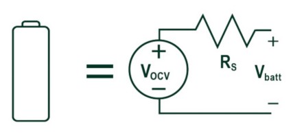
Figure 6. The RINT Model (versus Other Models)
The RINT Model: Accurately Simulating Battery Characteristics
The Internal Resistance (RINT) model provides a simulation of the battery’s internal chemical resistance, along with additional pack resistances created by internal connections, contactors, and safety components.
As seen in Figure 6, the RINT model can be implemented with a true bi-directional source
(Vocv) and a programmable series-resistance (Rs). This model is sufficient for understanding the major characteristics of battery-based resistances and pack resistances when testing powertrain systems.
While the number of mathematical models has increased, these more complicated models are used to understand the electro-chemical characteristics of batteries, the nuances of which have little impact on the overall system when compared with the total resistance of the pack.
NI battery emulators features this equivalent RINT Model providing anelectronically programmable “Battery Emulation” mode. Requiring only two simple terms (Vocv and Rs), the battery emulation automatically adjusts the terminal voltage (Vbatt) based on the direction and level of current (Icharge).
Vbatt = Vocv + Rs * Icharge
Performance Demonstration of Series Resistance Effect (RINT Model)
As in a real battery, NHR’s battery emulators adjust the output voltage depending on the direction and amplitude of current flow.
The current is shown as red in Figure 7, starting with the current being drawn from the simulated battery (50 A), increasing to a higher current (100 A), and finally dropping to zero. The output was set to simulate 5 m2 of resistance. The output voltage (shown in blue) shows the output as it tracks these current changes and provides the appropriate terminal voltage drop. This automatic adjustment of output voltage better simulates real-world battery pack characteristics—especially when compared with common DC bus and source/load simulation systems.
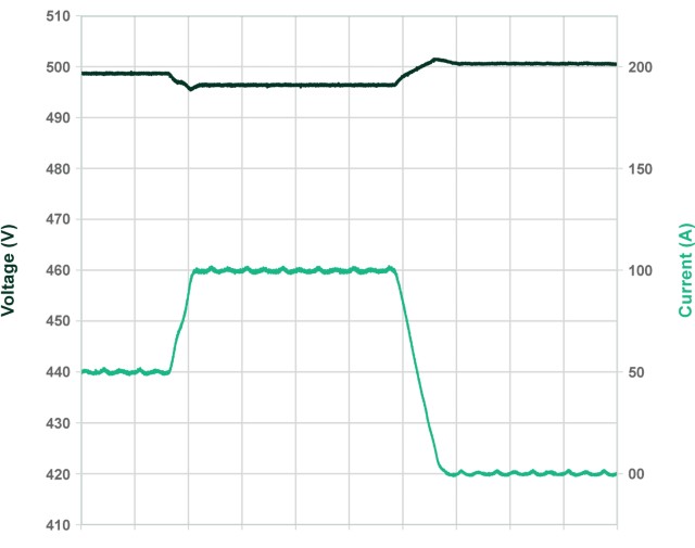
Figure 7. Performance of RINT Model
Flexible Solutions from NI
The battery emulation systems from NI are modular, meeting the voltage and current levels required by your testing needs. Higher-power models provide dual ranges, allowing the equipment to emulate today’s batteries and providing the right tool that grows along with increases in battery voltage and power.
Furthermore, NI provides a wide range of software control options, allowing this power stage to be fully integrated with the dynamometer and other test system components.
Modularity
All NI battery emulation systems are designed for fully independent operation and can be paralleled, increasing the maximum power and current capability to the level required. This modular expansion through paralleling ensures that you can start testing to today’s application levels, knowing that additional power is available if needed in the future.
For example, as shown In Figure 8, three systems can be operated as three separate test channels, one test channel at three times the power, or configured as two channels with one acting as a two times power and the other as a separate test channel. The NHR-9300 permits up to 12 channels to be combined in this way for a maximum total power of 2.4 megawatts.
Systems are future-proofed, sized for today’s needs and future power levels, without requiring the entire system to be replaced.
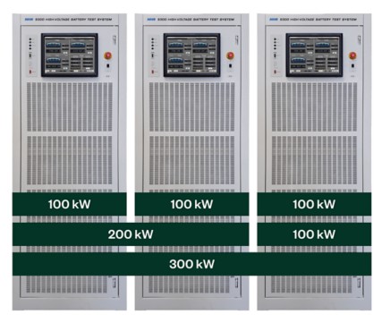
Figure 8. Systems are future-proofed
NI also manufactures lower-power systems with a wide range of voltage options. The modular NHR-9200 Mid-Voltage DC Battery Module Cycler and Emulator is expandable in 8 kW or 12 kW block sizes and has voltage options from 40 V to 600 V DC. This system uses the same drivers, touch panel controls, and software options, making it ideal for both high-power and low-power battery emulation systems.
Dual Ranges
Unlike competitive systems that are often purpose-built, NI high-power test systems ensure long-term value by providing a dual range, as shown in Figure 8. The full 100 kW power per module is available from 300 V to 600 V in the high current range as well as from 600 V to 1200 V in the high-voltage range. Dual ranges ensure that today’s EV drive trains (400 V–500 V) and next-generation models (800 V to 1000 V) can be easily tested using the same capital equipment.
Easy Integration: Software Control Options and Integration Partners
All NI battery emulators can be easily integrated into existing test platforms or used as the power stage for new test platforms. To achieve this, NI provides fully documented drivers using either IVI or SCPI languages along with examples, applications, and integration support.
NI also has several integration partners who are familiar with our hardware and can deliver a turnkey test system. These integrators develop fully custom systems—utilizing your specified hardware sensors and fixturing components.
Accurate Battery Simulation and Energy Savings
All NI battery emulators implement the RINT model, or series resistance effect, to provide the most accurate battery simulation. Furthermore, NI battery emulation solutions are regenerative, meaning any power flowing into the system is recycled into clean, usable facility power.
Summary
EV powertrains are evolving and have new testing challenges. Voltage and power levels are changing because of fast charging and vehicle performance. Traditional powertrain test approaches rely on unidirectional devices that have drawbacks and limitations. Modern battery emulation is a bidirectional approach that is isolated, can handle back-EMF, and is a more robust topology.
NI provides next-generation battery emulation solutions with the following capabilities:
- Flexibility to address changing voltage needs
- Scalability to address future power levels
- A series resistance model to simulate a battery more accurately
- Faster response times than DC power supplies
- Easier integration and software control
- Reduced energy costs
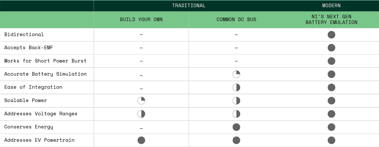
Table 1. Summary of EV Powertrain Test Approaches