niDCPower Configure Output Function VI
- Updated2025-10-06
- 4 minute(s) read
Configures the function that the specified channels attempt to generate.
Inputs/Outputs
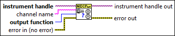
 instrument handle
—
instrument handle
—
instrument handle identifies a particular instrument session.  channel name
—
channel name
—
channel name specifies to which channel(s) to apply this configuration value. Specify the channel(s) using the form PXI1Slot3/0,PXI1Slot3/2-3,PXI1Slot4/2-3 or PXI1Slot3/0,PXI1Slot3/2:3,PXI1Slot4/2:3, where PXI1Slot3 and PXI1Slot4 are instrument resource names and 0, 2, and 3 are channels. If you do not wire this parameter, all channels in the session are used.  output function
—
output function
—
output function configures the function to generate for the specified channel(s). The default value is DC Voltage (1006).
 error in (no error)
—
error in (no error)
—
error in describes error conditions that occur before this node runs. This input provides standard error in functionality.  instrument handle out
—
instrument handle out
—
instrument handle out passes the handle used to identify the session in all subsequent NI-DCPower VI calls.  error out
—
error out
—
error out contains error information. This output provides standard error out functionality. |
Details
When DC Voltage is selected, a channel generates the desired voltage level on the output as long as the output current is below the current limit. The following VIs can be used to configure the channel when DC Voltage is selected:
- niDCPower Configure Voltage Level
- niDCPower Configure Current Limit
- niDCPower Configure Voltage Level Range
- niDCPower Configure Current Limit Range
When DC Current is selected, a channel generates the desired current level on the output as long as the output voltage is below the voltage limit. The following VIs can be used to configure the channel when DC Current is selected:
- niDCPower Configure Current Level
- niDCPower Configure Voltage Limit
- niDCPower Configure Current Level Range
- niDCPower Configure Voltage Limit Range
When Pulse Voltage is selected, a channel generates pulses at the desired pulse voltage levels on the output as long as the output current is below the pulse current limit. The following VIs can be used to configure the channel when Pulse Voltage is selected:
- niDCPower Configure Pulse Voltage Level
- niDCPower Configure Pulse Bias Voltage Level
- niDCPower Configure Pulse Current Limit
- niDCPower Configure Pulse Bias Current Limit
- niDCPower Configure Pulse Voltage Level Range
- niDCPower Configure Pulse Current Limit Range
When Pulse Current is selected, a channel generates pulses at the desired pulse current levels on the output as long as the output voltage is below the pulse voltage limit. The following VIs can be used to configure the channel when Pulse Current is selected:
- niDCPower Configure Pulse Current Level
- niDCPower Configure Pulse Bias Current Level
- niDCPower Configure Pulse Voltage Limit
- niDCPower Configure Pulse Bias Voltage Limit
- niDCPower Configure Pulse Current Level Range
- niDCPower Configure Pulse Voltage Limit Range
When Constant Resistance is selected, a channel generates the desired resistance level on the output as long as the output current is below the current limit. The following properties can be used to configure the channel when Constant Resistance is selected:
When Constant Power is selected, a channel generates the desired power level on the output as long as the output current is below the current limit. The following properties can be used to configure the channel when Constant Power is selected: