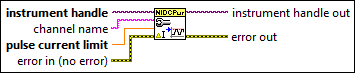
niDCPower Configure Pulse Current Limit VI
- Updated2025-10-06
- 3 minute(s) read
Configures the pulse current limit for the specified channel(s). A channel must be enabled for the specified current limit to take effect.
Refer to the niDCPower Configure Output Enabled VI for more information about enabling the channel. The pulse current limit is the current that the output must not exceed when generating the desired pulse voltage level. The pulse current limit setting is only applicable if the channel is set to the Pulse Voltage output function using the niDCPower Configure Output Function VI.
Inputs/Outputs
 instrument handle
—
instrument handle
—
instrument handle identifies a particular instrument session.  channel name
—
channel name
—
channel name specifies to which channel(s) to apply this configuration value. Specify the channel(s) using the form PXI1Slot3/0,PXI1Slot3/2-3,PXI1Slot4/2-3 or PXI1Slot3/0,PXI1Slot3/2:3,PXI1Slot4/2:3, where PXI1Slot3 and PXI1Slot4 are instrument resource names and 0, 2, and 3 are channels. If you do not wire this parameter, all channels in the session are used.  pulse current limit
—
pulse current limit
—
pulse current limit specifies the pulse current limit, in amps, on the specified channel(s). The limit is specified as a positive value, but symmetric positive and negative limits are enforced simultaneously.  error in (no error)
—
error in (no error)
—
error in describes error conditions that occur before this node runs. This input provides standard error in functionality.  instrument handle out
—
instrument handle out
—
instrument handle out passes the handle used to identify the session in all subsequent NI-DCPower VI calls.  error out
—
error out
—
error out contains error information. This output provides standard error out functionality. |