Part 4: Validating and Analyzing Dynamic System Models (Advanced Signal Processing Toolkit or Control Design and Simulation Module)
- Updated2023-03-14
- 4 minute(s) read
After estimating the dynamic system model, perform model validation to test the estimated system model. Model validation verifies whether the model provides an accurate description of the dynamic system. You also can perform model analysis to analyze the dynamic properties of the dynamic system model.
Validating Dynamic System Models
Complete the following steps to validate the system model.
- Add the SI Model Simulation VI to the block diagram of the VI you created.
 Add
Add
- Wire the system model out output of the following VIs or Express VIs to the system model input of the SI Model Simulation VI.
- SI Estimate State-Space Model VI
- SI Estimate Transfer Function Model VI
- SI Model Estimation Express VI
- SI Transfer Function Estimation Express VI
- Wire the stimulus signal output of the SI Data Samples VI to the stimulus signal input of the SI Model Simulation VI.
- Add the Build Array function to the block diagram.
- Wire the response signal output of the SI Data Samples VI to the element input of this function.
- Add an input to this function node by resizing the node and wire the response output of the SI Model Simulation VI to the new element input.
- Add a Waveform Graph indicator to the front panel. The block diagram displays a node of this indicator.
- Right-click in this Waveform Graph and select Properties from the shortcut menu to display the Graph Properties: Waveform Graph dialog box.
- Place a checkmark in the Show graph palette checkbox in the Appearance page.
- Click the OK button to close this dialog box and save the configuration.
- Switch to the block diagram and wire the appended array output of the Build Array function to this indicator. The following figure shows the block diagram.

- Wire all error in and error out terminals on the block diagram.
- Run this VI to generate the simulated response signal.
To validate the system model, compare the simulated response signal and the acquired response signal in the waveform graph. Use the zoom button on the graph palette to zoom in on the signals. The following figure shows the resulting waveform graph.

Because of the friction of the DC servomotor in the start-up stage, the acquired response signals and the simulated signals deviate at the beginning of the two signals. The later parts of the simulated response signals and the acquired response signals match each other. Therefore, this dynamic system model provides an accurate description of the dynamic system.
Analyzing Dynamic System Models
Use model analysis to observe the model characteristics, such as frequency response.
Complete the following steps to analyze the system model.
- Add the SI Bode Plot VI to the block diagram of the VI you created.
Add
- Wire the system model out output of the following VIs or Express VIs to the system model input of the SI Bode Plot VI.
- SI Estimate State-Space Model VI
- SI Estimate Transfer Function Model VI
- SI Model Estimation Express VI
- SI Transfer Function Estimation Express VI
- Add an SI Bode Plot Indicator to the front panel. The block diagram shows two indicators.
- Wire the Bode magnitude plot and Bode phase plot outputs to the corresponding indicators. The following figure shows the block diagram.

- Wire all error in and error out terminals on the block diagram.
- Run this VI to generate the bode plots of this dynamic system model.
To analyze the system model, read the magnitude and phase information from the bode plots. The following figure shows the resulting bode plots.
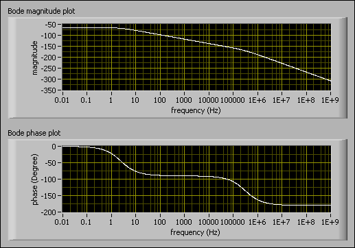
In the magnitude plot, the curve remains stable in the low frequency bands and falls slowly in the high frequency bands. In the phase plot, the curve falls near –90 degrees in the low frequency bands and falls near –180 degrees in the high frequency bands. These two plots indicate the following characteristics of this dynamic system:
- The order of this dynamic system is two.
- When the frequency is below 1000 Hz, you can treat the order of this dynamic system as one.
Use other Model Analysis VIs to analyze other characteristics of the dynamic system models, such as the SI Nyquist Plot VI and the SI Pole-Zero Plot VI.
| Previous: Identifying Dynamic System Models | Next: Converting Dynamic System Models to Control Design Models |