Part 2: Exciting the System and Acquiring Data (Advanced Signal Processing Toolkit or Control Design and Simulation Module)
- Updated2023-03-14
- 5 minute(s) read
After you choose a proper dynamic system model, you must acquire the input and output data from the direct current (DC) servomotor. You then preprocess and use the data to estimate unknown coefficients of the dynamic system model. You can use an encoder or a DC tachometer to measure the shaft speed of the DC servomotor.
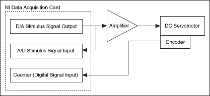
Set up the following experimental circuit to excite the DC servomotor and acquire response signals with an encoder.
Set up the following experimental circuit to excite the DC servomotor and acquire response signals with a DC tachometer.

Both circuits use an NI data acquisition (DAQ) card to generate digital stimulus signals. You also can use a reconfigurable I/O (RIO), CompactRIO, or Single-Board RIO device to generate the stimulus signals and acquire data. In these two circuits, a D/A output channel of the NI-DAQ card converts the stimulus signals to analog voltage signals and sends these signals to an amplifier. An A/D input on the NI-DAQ card acquires the original analog signals, converts the signals to digital signals, and records these digital signals for identification. The amplifier sends the enhanced analog signals to drive the DC servomotor. If you use an encoder to measure the shaft speed of the DC servomotor, the encoder generates pulses when the DC servomotor rotates. The encoder sends the pulses to a digital input channel of the NI-DAQ card. A counter in the NI-DAQ card counts the number of pulses and computes the rotational speed of the DC servomotor. If you use a DC tachometer to measure the shaft speed of the DC servomotor, the DC tachometer generates back-EMF voltage signals when the DC servomotor rotates. The DC tachometer sends the voltage signals to another A/D channel of the NI-DAQ card. The NI-DAQ card calculates the rotational speed by using the voltage signals.
 |
Note Ensure the NI-DAQ card acquires stimulus voltage signals and rotational speed synchronously. Ensure you acquire and save synchronous stimulus signals and response signals with constant time steps. |
You can use the following types of stimulus signals:
- Step signals—Use step stimulus signals for the low frequency band of a linear dynamic system. This type of signal is easy to generate but has a low signal-to-noise ratio (SNR) in the high frequency bands. To generate a step signal, create an array that begins with a series of zeros and then shifts to a series of ones, such as "0, 0, 0, 0, 0, 0, 1, 1, 1, 1, 1, 1, 1, 1, 1". An element in this array represents a sampling point. Ensure the array contains enough elements according to the sampling rate of the device you use. You then use the Build Waveform (Analog Waveform) function to convert this array to a waveform signal.
- Swept sine signals—Use swept sine stimulus signals for the full frequency bands of a linear dynamic system. This type of stimulus signal has a high SNR in the full frequency bands of a linear dynamic system. However, if the response signals contain non-linear distortion, this type of stimulus signal cannot eliminate the distortion and leads to an inaccurate dynamic system model. Use the Chirp Pattern VI to generate an array containing a swept sine pattern. You then use the Build Waveform (Analog Waveform) function to convert this array to a waveform signal.
- Random signals—Use random stimulus signals for the full frequency band of dynamic systems. This type of stimulus signal has a high SNR in the full frequency band. You must repeat exciting the dynamic system and acquiring data for multiple times to cover the full range of the dynamic system and eliminate any non-linear distortion in the response signals. Use the Periodic Random Noise VI to generate an array of periodic random noise. You then use the Build Waveform (Analog Waveform) function to convert this array to a waveform signal.
In this example, you can use any of these three types of stimulus signals to excite the DC servomotor.
Refer to the following VIs for examples of generating stimulus signals and acquiring data from a dynamic system. You must have the required hardware, such as an NI-DAQ card, to use these examples.
- Stimulus Signal Generation (DAQmx) VI: labview\examples\System Identification\Getting Started\General.llb
 Open example
 Find related examples
- Stimulus and Response Data (DAQmx) VI: labview\examples\System Identification\Getting Started\General.llb
Open example
Find related examples
- Stimulus and Response Data with Encoder (DAQmx) VI: labview\examples\System Identification\Getting Started\General.llb
Open example
Find related examples
Alternately, if you do not have the required hardware or a DC servomotor, use the SI Data Samples VI to generate the input and output data. This tutorial uses the SI Data Samples VI to complete the following parts. If you also use this VI to complete the following parts, you can get identical results as the results in this tutorial.
Complete the following steps to generate the input and output data by using the SI Data Samples VI.
- Create a blank VI in LabVIEW.
- Add the SI Data Samples VI to the block diagram of the VI you created. This VI generates single-input single-output waveform signals by default.
 Add
Add
- Right-click the data input of this VI and select Create»Constant from the shortcut menu to create a constant for this input.
- Ensure the value of this constant is Motor.
You can save this VI and use this VI to complete the following parts of this tutorial.
| Previous: Choosing a Proper System Model by Using Physical Modeling | Next: Identifying Dynamic System Models |