Closing a Critical Coverage Gap in ADAS/AD Camera Validation
Overview
Part of our H1 2023 Automotive Journal
Testing production release software for camera-based advanced driver assistance systems (ADAS) is difficult due to the integrated safeguards for meeting functional safety requirements. To satisfy the validity checks of the device under test and stimulate behaviors similar to test driving, NI provides dedicated hardware and software for emulating image sensor functionality on three different layers, helping to avoid the need for a dedicated testing mode software build for validation (known as HIL-mode).
Contents
- Why ADAS Camera Validation is a Challenge
- How to Enable ADAS Camera Validation using ECU Release Software
- Conclusion
- Next Steps
Why ADAS Camera Validation is a Challenge
Vision-based Advanced Driver Assistance Systems are an integral part of modern vehicles and supplement the vehicle’s view of the world in the visible electromagnetic spectrum. They provide important autonomy functions, improving road safety through automated vehicle trajectory planning based on object detection and classification. At the core of many ADAS Electronic Control Units (ECUs) lies an ASIC accelerating Neural Network (NN) inference on sensory input. Mobileye Global, Inc., provides one of the most widely used chipsets for these NN-based subsystems.
For car manufacturers and suppliers, validation and homologation of such systems present a new class of challenges. From conventional quality assurance methods, only testing is effectively applicable to NN-based ADAS ECUs. A lot of investments are made in the testing phase before start of vehicle production. One popular approach because of economic and reproducibility reasons is functional testing in a lab-based environment, clustering relevant ECUs in a hardware-in-the-loop (HIL) setup while the rest of the vehicle bus is simulated. The sensor stimulus is then injected into the ECUs on a digital path.
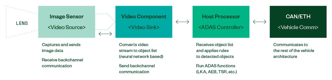
Figure 1: Typical Architecture of an ADAS Camera System (Simplified)
ADAS ECUs responsible for safety critical vehicle functions are required to self-diagnose faults and relinquish control of the vehicle in a safe manner (failsafe). Therefore, for a vision ECU, observing the operational status of the image sensor(s) and validating the provided video stream must happen in real time.
Modern image sensors provide multiple ways of securing the data paths to and from the downstream video processor against errors: Some manufacturers enable CRC checksums on the side-channel transactions. The video stream can be configured to include alive counters and configuration state snapshots in the image. Some sensors include an ERROR interrupt output pin. The MIPI CSI2 specification additionally provisions for CRC guards and frame counters on the protocol level.
These and other safeguards are employed to make sure that autonomous vehicles can yield control to the driver quickly to avoid following a ghost trajectory due to faults in the image path. Simply injecting a video stream or a previous recording into an ECU will, thus, trigger the failsafe mechanism.
This challenge has been known from day one and the obvious remedy was to turn off ECU software health monitoring and status validation altogether. This state is better known as “HIL-mode” for vision ECUs, and it is also supported by Mobileye and other vendors like Bosch or Continental. While this is a valid mechanism to enable perception layer and application software testing, the inherent downside of this approach is that the software release under test is not the software that will be deployed in the field later. Therefore, validation tests miss parts of the test coverage, which are only present in the production software.
One solution here is to reverse engineer and emulate the image sensor’s behavior in real time to enable production-release ECU software testing.
How to Enable ADAS Camera Validation using ECU Release Software
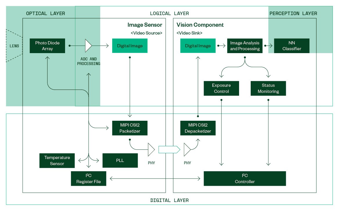
Figure 2: Simplified View into an Image Sensor and a Downstream Vision Component
Figure 2 depicts a simplified conceptual model of an image sensor acting as the video source and a connected vision component as the video sink. At the logical level, digital images are produced in the image sensor and consumed by the vision component.
Each incoming image is analyzed before being forwarded to the perception layer. Specific image properties, such as the average brightness, histogram, and so on, are fed to a control module responsible for tuning the image sensor to produce properly exposed images suitable for object classification.
Status monitoring will extract alive counters and validate the sensor’s configuration state by extracting information from embedded data within the image. This module makes it difficult to provide any generic video stream to the ECU in a HIL environment without using prerelease software including ECU "HIL-mode."
An injection system needs to emulate the behavior of multiple sensor sub-components in real time to avoid triggering failsafe measures in the vision component and produce reliable test results for detection performance.
Simulation of the optical layer is the domain of the host computer generating the sensor input data. In open-loop regression tests, a previous recording from a similar camera ECU is replayed to the DUT. Generating live synthetic data using a visualization tool enables closed-loop tests for scenario exploration, functional, and performance testing. The quality of the generated data is directly linked to the fidelity of the optical sensor model.
The optical properties that are usually covered, to varying degrees, in a synthetic simulation are shown in Figure 3.
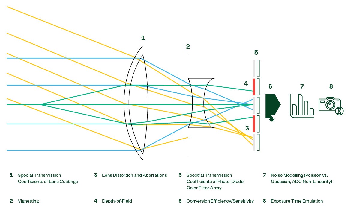
Figure 3: Effects on the Opto-Electrical Path
On the logical layer, the bulk of emulation efforts will usually be dominated by on-line digital image manipulation. Some vision systems might have the sensor dynamically crop the image and place the readout window across the active pixel array. Sensors with color filters provide individual color channel amplification for white balance tuning in varying lighting environments.
The intensity of the incident light may sometimes exceed the capacity of the photodiodes to capture the whole dynamic range of the scene, especially at night. To increase the captured dynamic range, modern sensors allow for multiple analog-to-digital conversions during the exposure time. Each individual conversion yields 12 bits of brightness information that is then internally stacked to a final 20-bit digital image. To save bandwidth, the 20-bit image can then be compressed to 12 bit or 16 bit using a dynamically configurable, non-linear transfer function.
Downstream processors may depend on image statistics provided by the sensor to correctly control the exposure time. Image sensors can generate dynamically configurable histograms with the image output.
The digital layer is shaped by low-level protocol and electrical parameters. While these also dictate the PCB design for the ECU interface, the relevant configuration parameters internal to the sensor include online configuration of the MIPI CSI-2 communication module and the clock rates generated by the phase-lock loop (PLL), ultimately driving the output frame rate. Additionally, sensible outputs from the Register File must be provided, such as temperature sensor and status flags readouts.
Real-time embedded systems have tight design timing constraints (latency and throughput) that need to be respected when building instrumentation interfaces. In addition to emulating the image sensor functionally, great care must be employed to react to requests and provide data streams within the timing constraints of the target device under test.
NI’s solutions portfolio covers all the aforementioned topics providing modular and customizable testing systems for ADAS/AD ECUs (see Figure 4).
Leveraging a strong partner network, NI can provide customized instrumentation interfaces for all but the most tightly integrated ECUs.
The real-time core of the image sensor emulation IP is realized on a dedicated high-performance scalable hardware platform capable of supplying multiple UHD video streams in parallel, covering the needs for modern vehicle vision systems. In addition, the emulation core is capable of deliberately inserting faults into various processing stages to enable test coverage of the error handling mechanisms in the DUT.
On the simulation side, NI hardware provides scalability and openness to third-party software simulations that can be connected to the loop via a bi-directional high bandwidth RDMA over Converged Ethernet data link. Compatibility with optional third-party simulation tools is given by adapting HDMI data sources.
Conclusion
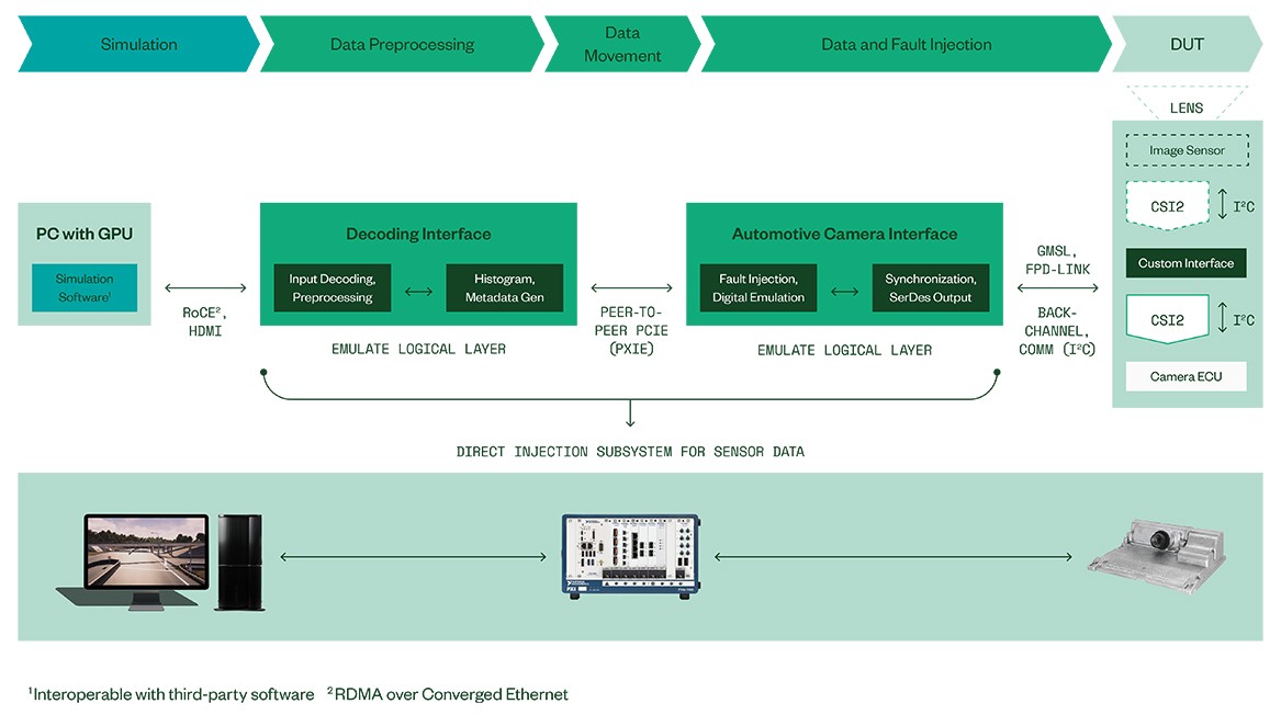
Figure 4: NI HIL System Architecture for Direct Data Injection Using Production Release ECU Software
In summary, ADAS ECUs, being safety-critical systems, use status monitoring safeguards that make video injection a non-trivial task. A sophisticated, multi-layered, real-time image sensor emulation model must be used to satisfy the validity checks in the ECU and to generate video streams that elicit behavior from the perception layer similar to real-world test driving.
NI’s sophisticated optical simulation and real-time emulation for image sensors allows for comprehensive verification of current and future vision based ADAS/AD ECUs worldwide. NI solutions enable validation tests based on production software for vision ECUs, which closes a coverage gap that has existed since the introduction of “HIL-mode” using pre-release software.