Different Types of Isolation: Channel-to-Channel, Bank (Channel-to-Bus), and Channel-to-Earth Ground
Overview
Contents
- Introduction
- Channel-to-Earth Ground Isolation
- Bank (Channel-to-Bus) Isolation
- Channel-to-Channel Isolation
- Additional Resources
Introduction
This article contains basic information about isolation. For a more in depth look at the isolation, please refer to Isolation Types and Considerations when Taking a Measurement.
Isolation is the means of physically and electrically separating two parts of a device. It protects computer circuitry and human operators, breaks ground loops, and improves common-mode voltage and noise rejection. It can be categorized into electrical and safety isolation. This KnowledgeBase article discusses electrical isolation. For electrical isolation, parts of a device are separated with isolation barriers that separate the card into sections. Multiple buses service each section individually. The 3 types of isolation can be listed from basic (low level protection) to complete (high level protection) in the order of: Channel to Earth Ground, Bank, and Channel to Channel isolation.
All NI isolated devices are isolated from Earth Ground. They are also either Bank Isolated (with 1 or more banks) or Ch-Ch Isolated.
Channel-to-Earth Ground Isolation
Channels of the device and the device's Earth ground are electrically isolated from one another. Channel-to-Earth isolation is represented in the Figure 1. Voltages of the isolated front end (Va-c ) are on the same bus; these voltages are not isolated from one another. Ve,d are on a separate bus and are isolated from the front end. This is the most fundamental type of isolation and this protection is covered by bank and channel-to-channel isolation. Channel-to-Earth Ground Isolation can also be thought of as Channel-to-Bus isolation with only one bank, as in the case of the NI 6230. Normally, this isolation type is present on NI 9000 series modules and some SCC modules.
Note: For the following diagrams, the diagonal hash marks indicate the isolation barrier, this separates circuitry. The transformer symbols represent electromagnetic isolation used to couple a signal across the isolation barrier by generating an electromagnetic field proportional to the electrical signal.
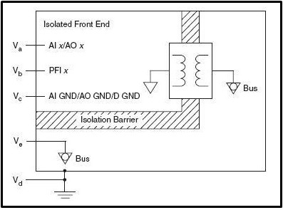
Figure 1. Schematic of Channel-to-Earth Isolation
Bank (Channel-to-Bus) Isolation
Channels of a device are banked (grouped) together to share a single isolation amplifier. Figure 2 represents Bank isolation. In this topology, the common-mode voltage difference between channels is limited, but the common-mode voltage between the bank of channels and the non-isolated part of the measurement system can be large. In other words, individual channels are not isolated, but the channel groups are isolated from one another and earth ground. Bank1, Bank2, Vi, and Vj,k are on separate buses and isolated from one another.
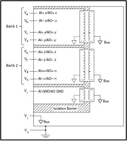
Figure 2. Schematic of Bank (Channel to Bus) Isolation
Channel-to-Channel Isolation
Each channel is isolated from every other channel and other non-isolated components. Figure 3 represents channel-to-channel isolation. Va,b, Vc,d, Ve,f, and Vg,h are all on separate buses and are isolated from one another.
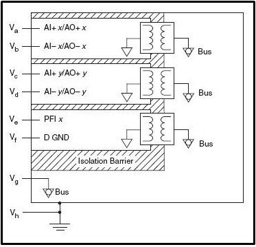
Figure 3. Schematic of Channel-to-Channel Isolation
Note: If the device has a channel-to-channel specification and has AI, AO, and DI/O, such as the NI 6154, the DI/O channels are bank isolated from the other channel-to-channel isolated AI and AO channels.