Making Accurate Strain Measurements - Improving SNR and Determining Optimal Excitation Levels
Contents
- Reducing Signal to Noise Ratio (SNR)
- Choosing an Optimal Excitation Level
- Experimental Method for Determining the Optimal Excitation Voltage
- Summary
- Other Strain Resources:
Reducing Signal to Noise Ratio (SNR)
Signal to Noise Ratio (SNR) is a term that is used to describe the ratio of the amplitude of the signal to the amplitude of the noise. A larger SNR typically results in a less noisy measurement, which enables you to better overall resolution. Noise in strain readings can be particularly troublesome because of the small signals that are involved in strain measurements. The SNR can be improved by either increasing the overall amplitude of the signal before the noise is introduced into it, or by reducing the amplitude of the noise.
A common source of noise in many applications is the measurement device. Noise introduced by the measurement device adds to the overall error of your measurements, and can obscure the smaller amplitude signals which will reduce the overall dynamic range of your measurement device.
Noise that is introduced from an external source can often be associated with specific frequencies, and therefore can be filtered out in software if the frequency of the noise is predictable, and does not interfere with the bandwidth of the signal of interest. The most common type of noise is power line interference, which will show up as 50Hz or 60Hz noise in the measurements.
Techniques for improving SNR:
- Reduce the length of the strain gauge’s lead wire, and keep the wire away from any potential noise sources.
- Enclose the lead wire in a shield which is tied to the chassis of the measurement device.
- Use a measurement device with a large dynamic range. Dynamic range defines the noise level relative to the full input range of the measurement device, and is often specified in terms of dB. For example, the NI 9237 has a Spurious Free Dynamic Range (SFDR) of 106dB, which is equivalent to noise levels of about 0.0005% of the full input range.
- Increase the amplitude of the signal. With strain measurements, this can be accomplished by increasing the amplitude of the excitation voltage. However, there are tradeoffs associated with increasing the amplitude of the excitation voltage, so this document will also discuss how to identify the optimal excitation voltage for your application.
The importance of gain in strain measurements
One of the main reasons for applying gain to a signal is to scale a small signal to take advantage of the full input range of the analog to digital converter (ADC) in order to increase the resolution of the input signal. If the ADC of the input device has a variable input range, or a very large resolution, then gain sometimes is not necessary. For example, an input range of +-50mV on a 16bit ADC correlates to a resolution of 1.5uV, which is equivalent to the resolution obtained with an input range of +-12.8V using a 24bit ADC.
If the signal path is prone to introducing noise into the measurement, then applying gain early on in the signal path before the noise is introduced can help increase the overall SNR. However, most gain circuits will also introduce noise and offset errors of their own, so they need to be carefully designed in order to minimize the added errors.
In general, the two main factors that should be used to determine which measurement device you plan to use are 1) available signal ranges and 2) overall noise-free bits of resolution, often referred to as Effective Number of Bits (ENOB). Filtering can also be important to improving accuracy by reducing aliasing, but most noise that is not aliased can be filtered out or averaged out in software.
Choosing an Optimal Excitation Level
The change in output voltage for a given level of strain increases in direct proportion to the excitation voltage. Increasing excitation voltage thus improves signal to noise ratio, but a practical limit is reached when the ill effects of gauge self-heating become predominant.
A common request in strain gauge work is to obtain the recommended value of bridge excitation voltage for a particular size and type of gauge. Unfortunately, a simple answer to this question is not possible because there are many different factors that will affect the optimal excitation level for a particular strain gauge configuration.
This section of the document is intended to outline the most significant considerations which apply, and to suggest specific approaches to optimizing excitation levels for various strain gauge applications.
It is important to realize that strain gauges are seldom damaged by excitation voltages considerably in excess of proper values. The usual result is performance degradation, rather than gauge failure; and the problem therefore becomes one of meeting the total requirements of each particular installation.
Factors Affecting Optimum Excitation
Following are factors of primary importance in determining the optimum excitation level for any strain gauge application:
- Strain gauge grid area. (Active gauge length x active grid width.)
- Gauge resistance. High resistances permit higher voltages for a given power level.
Heat-sink properties of the mounting surface. Heavy sections of high-thermal-conductivity metals, such as copper or aluminum, are excellent heat sinks. Thin sections of low-thermal-conductivity metals, such as stainless steel or titanium,are poor heat sinks. Also, the shape of the gauge part may create thermal stresses in portions of the structure due to gauge self-heating. Long warm-up times and apparent gauge instability can result. The situation often arises in low-force transducers, where thin sections and intricate machining are fairly common.
Strain measurement on plastic requires special consideration. Most plastics act as thermal insulators rather than heat sinks. Extremely low values of excitation are required to avoid serious self-heating effects. The modulus of elasticity of the common plastics drops rapidly as temperature rises, increasing visco-elastic effects. This can significantly affect the material properties in the area under the strain gauge. Plastics which are heavily loaded with inorganic fillers in powder or fibrous form present a lesser problem, because such fillers reduce expansion coefficients, increase the elastic modulus, and improve thermal conductivity.Environmental operating temperature range of the gauge installation. Creep in the gauge backing and adhesive will occur at lower ambient temperatures when grid and substrate temperatures are raised by self-heating effects. Thermal output due to temperature will also be altered when grid and substrate temperatures are significantly different.
Required operational specifications. Gauges for normal stress analysis can be excited at a higher level than under transducer conditions, where the utmost in stability, accuracy, and repeatability is needed.
A significant distinction exists between gauges used in dynamic strain measurement and those used in static measurement applications. All the various performance losses due to gauge self-heating affect static characteristics of the gauge much more seriously than the dynamic response. Therefore, it is practical to "drive" the dynamic installations much harder, and thus take advantage of the higher signal-to-noise ratio which results.Installation and wiring technique. If the gauge is damaged during installation, if solder tabs are partially unbonded due to soldering heat, or if any discontinuities are formed in the glueline, high levels of excitation will create serious problems. Proper technique is essential in obtaining consistent performance in all strain gauge work, but particularly under high-excitation conditions.
Experimental Method for Determining the Optimal Excitation Voltage
An optimum excitation voltage is best determined by an experimental procedure. With no load applied, you should examine the zero point of the channel while excitation level is progressively raised. Once instability in the zero reading is observed, you should lower the excitation until stability returns. It is best to perform this experiment at the highest temperature over which you are taking measurements. Also, using larger gauges and higher resistance gauges -- 350 instead of 120 ohms -- decreases the power per unit area dissipated, and higher excitation voltage is possible.
Theoretical Strain Gauge Excitation Values
A good starting point for determine the optimal excitation voltage is to determine a rough theoretical limit. Calculations can be made according to the following formulas for recommended power-densite levels:
Power Dissipated in Grids (watts)

Power Density in Grids (watts per unit area)

where:
![]() = Gauge Resistance in ohms
= Gauge Resistance in ohms
 = Grid Area (active gauge length x grid width)
 = Bridge Voltage in volts for an equal-arm bridge arrangement, where the voltage across the active arm is half the bridge voltage.
When the grid area, gauge resistance, and grid power density are known, the bridge excitation is:
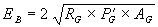
This value represents a general recommendation or starting point for determining optimum excitations levels for grid areas having constant power-density levels.
Instruments with Fixed Bridge Excitation
When the bridge voltage of an instrument is fixed at a value that is higher than recommended, several alternatives are available:
- Select a higher resistance gauge.
- Select a gauge with a larger grid area.
- Reduce the bridge voltage with an inactive series resistor.
The inactive resistor (  ) required to reduce the power density to the desired range can be determined from the following relationship:
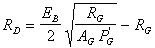
Select the nearest precision resistor value (  ) higher than the calculated value ( ).
For actual strain values (  ), accounting for the actual value of the inserted inactive resistor ( ), all indicated strain readings (
  ) must be multiplied by an attenuation factor,
  , where:

and

Stacked Rosette Gauges
These represent a special case, because the thermal path length is much greater from the upper grid to the substrate, and because the temperature rise of the lower grids adds directly to those above. For a three-element stacked rosette in which the three grids are completely superimposed, the top grid will have six times the temperature rise of a similar single gauge, if all grids receive the same input power. To keep the temperature rise of the top grid equal to that of a similar single gauge, the three rosette sections should each receive 1/6 of the power applied to the single gauge. This corresponds to a reduction factor of 2.5 for bridge excitation voltage, since power varies as the square of the applied voltage. For two-element stacked rosettes, the comparable de-rating factor is 3 for power, and 1.7 for bridge voltage.
Note: This discussion is based on rosettes of square grid geometry, where each grid covers essentially all of the grid(s) in the assembly. When substantial areas of the grids are not superimposed, the derating factors mentioned above will be somewhat conservative.
Summary
Reducing noise and increasing resolution are important for making accurate strain measurements due to the very small voltage levels that are involved. Picking the right measurement device can greatly improve the integrity of your strain measurements, but gain and excitation level are not the most important factors in making accurate strain readings. You should pick a measurement device with a large dynamic range/resolution, and a small input range. Then if you take steps toward reducing the noise introduced into the system, you can reduce the excitation level to reduce self-heating errors and improve the accuracy of the signal from your strain gauge. For static or slow-changing strain measurements you may also consider over-sampling and averaging multiple readings.