Effects of Capacitance with NI's Digital Instrument Cables
Overview
Contents
- Effects of Lumped vs. Distributed Capacitance
- Effects of Lumped and Distributed Capacitance
- Effects of Power on Lumped vs. Distributed Capacitance
- Effects of Rise and Fall Times on Low Drive Strength
- Conclusion
Effects of Lumped vs. Distributed Capacitance
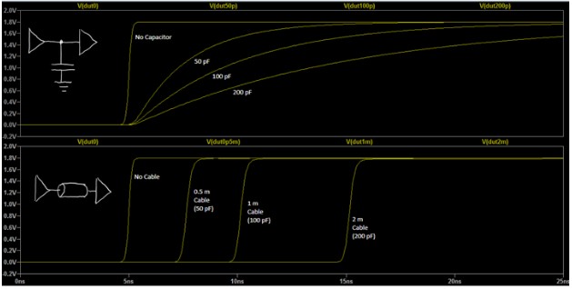
Lumped capacitance slows down voltage transitions, while distributed capacitance delays the voltage transitions. This is shown in Figure 1, which compares 0pF, 50pF, 100pF, and 200pF lumped vs. distributed. The top graph shows the lumped capacitor, while the bottom graph shows the distributed cable. It is apparent that although the overall capacitance is the same, the response is different.
Figure 1
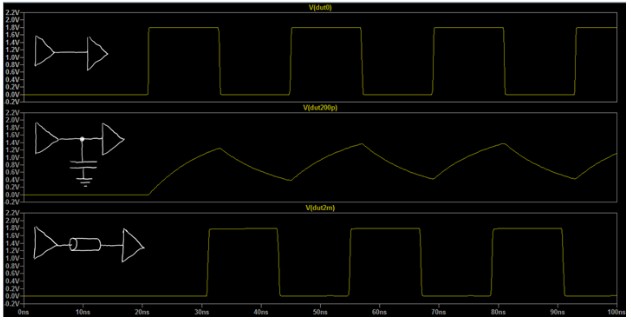
This is also the case when a clock is simulated with a 24ns period (42 MHz) with no load, while being driven with a 200pF capacitor and using a 2m cable with 200pF of capacitance, as seen in Figure 2 below. In this example, the top (no capacitance) and the bottom (2m cable with 200pF of capacitance) produce an identical, but delayed, response. To address the delayed response from the distributed cable, you can use the TDR feature of the Digital Pattern Instrument to compensate for the delays and display results in Digital Scope in the Digital Pattern Editor as if the cable were not present. A lumped capacitance (the middle signal) causes the signal to become distorted.
Figure 2
Effects of Lumped and Distributed Capacitance
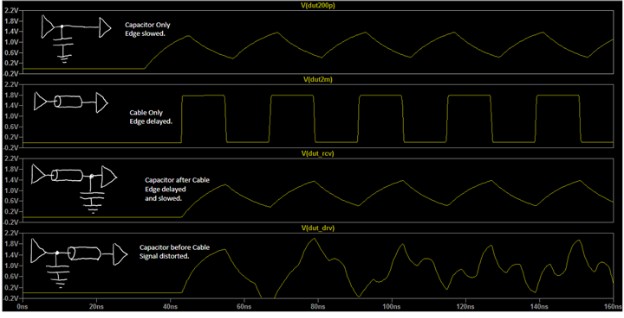
Figure 3 shows what will happen if you use a lumped capacitance with a cable. The test represents four different use cases: a signal with only a capacitor, a signal with only a cable, a signal with a cable followed by a capacitor, and a signal with a capacitor followed by a cable.
When the capacitor is at the receiving end of the cable, the delayed edge charges the capacitor just as the driver would, so the edge is both delayed and slowed. However, when the capacitor is at the driving end of the cable, there will be a large frequency-dependent impedance mismatch on the driving end of the cable as well as an impedance mismatch at the receiving end of the cable. Therefore, edges reflect back and forth, producing a potentially unexpected signal.
Figure 3
Effects of Power on Lumped vs. Distributed Capacitance
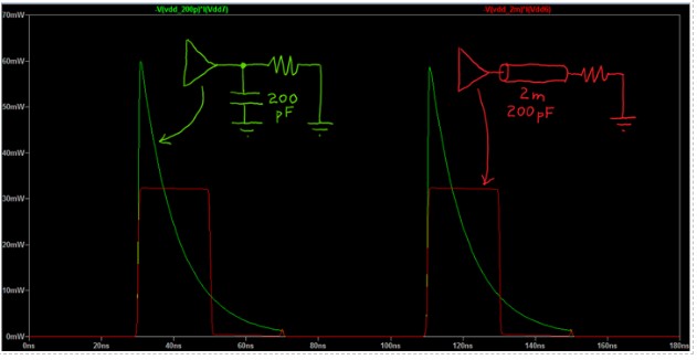
This section will show how power is affected by lumped vs. distributed capacitance. Figure 4 shows the power drawn from the supply of the Digital Pattern Instrument driver when driving a high impedance DUT with a 200pF capacitor, compared to through a 2m 200pF cable.
The green line is the test setup with the 200pF capacitor (lumped capacitance), while the red line is the test setup with the 2m 200pF cable (distributed capacitance). Figure 4 shows that the areas under the two curves are very similar, because the same amount of energy is required to charge 200pF whether it is lumped or distributed. However, the distributed capacitance did not significantly affect the shape of the signal, while the lumped capacitor has a higher peak power and discharges slowly.
The same energy is released from the capacitance each time the signal switches from high to low, but that is not shown here.
Figure 4
Effects of Rise and Fall Times on Low Drive Strength
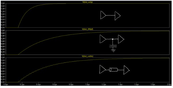
One important exception to the above information occurs when the DUT has a very low drive strength (high output impedance) and/or a very slow power on time. The effects can be seen in Figure 5. As the rise time of the DUT and its load board without the cable becomes longer relative to the propagation delay of the cable, the cable begins to behave like a lumped capacitance.
Figure 5
Conclusion
Distributed capacitance along a coaxial cable is not the same as lumped capacitance in one location. Many DUTs can be tested using cabling that exceeds their maximum specified capacitance if a delay is acceptable. Here are the key points to take away:
- Lumped capacitance slows down voltage transitions, while distributed capacitance delays voltage transitions. Please refer to Figures 1 and 2.
- The Digital Pattern Instrument solves this by using a TDR adjustment to account for the delay.
- A large lumped capacitance combined with a long cable may produce results which are unexpected or harder to predict. Refer to Figure 3.
- Distributed capacitance is still capacitance, so power will be dissipated while charging and discharging, just as with a lumped capacitor. Refer to Figure 4.
- If the DUT itself has a very slow rise time, the cable will behave more like a lumped capacitance. Refer to Figure 5.
If you are running into issues where the DUT does not have enough drive strength to properly drive the signal back to the digital pattern instrument, please try the following recommendations.
- For DUTs with programmable drive strength, increase the drive strength to better match the 50 Ohm interconnect.
- Try reducing the VOH and VOL thresholds.
- Try reducing the test fixture and cable lengths to accommodate for the slow rise times.
- Try reducing the rate of the digital pattern instrument to accommodate for the slow rise times.
