National Instruments has taken two specific actions to provide VXIbus trigger solutions. The first was to develop the triggering API in the NI-VXI driver (as well as the local command set for the GPIB-VXI).
The second action was to create the Trigger Interface Chip, or TIC ASIC. This chip has the ability to work with all the VXI-defined standard trigger protocols. The TIC also contains general-purpose counters and a cross-matrix switch for complex routing of trigger and clock signals. In addition, the TIC has 10 general-purpose input/output (GPIO) lines that can bring signals other than triggers into the TIC and can send trigger or counter signals out of the chip. On the National Instruments controllers, some of the GPIO lines already have been assigned to the external CLK10, the Front In, and Front Out connectors. The remaining GPIO lines are available for other uses.
The TIC chip comes standard on the GPIB-VXI and on the embedded computer line. This section looks at the features the TIC chip provides by examining the different NI-VXI functions for triggering, as well some examples illustrating the different uses of the API. For more information on the TIC chip, please see Appendix A.
Basic Trigger Functions
For a simple set of trigger functions, consider the case of generating triggers on the VXI backplane. Notice that systems without the TIC chip have triggering capabilities to the extent described here and in the following section, Program Control.
The function
SrcTrig() lets you source a trigger using any of the VXI-defined protocols. It can assert the protocol on any of the TTL lines and ECL0-12. On a system without the TIC chip, you can source or monitor a single trigger line at a time. With the TIC, it is possible to source and monitor multiple lines simultaneously. If the platform has the TIC chip, you can also source the GPIO lines.
Note: The GPIO lines cannot source or acknowledge ASYNC nor SEMI-SYNC because they do not have the edge detection or interrupt circuitry necessary to operate these protocols.
You can also use
SrcTrig() on the counter and timers in the TIC chip as described later in the TIC Counter Functions section. Also, because some of the trigger protocols are actually asynchronous handshaking, you can specify a timeout so that the function will wait for the acknowledge (see the discussions of the ASYNC and SEMI-SYNC protocols earlier in this document).
The following code is a simple example of sourcing a SYNC pulse.
Example 1 Sourcing the SYNC Trigger Protocol
/* Generate a SYNC pulse on TTL line 0 */
controller = -1;/* Local controller */
line = 0; /* TTL0 */
prot = 4; /* SYNC */
timeout = 0L; /* No timeout */
ret = SrcTrig (controller, line, prot, timeout);
Program Control
A common requirement is to have the controller source the trigger protocols. However, there are cases where another device will source the trigger and it is up to the controller to respond. NI-VXI supports both cases easily. In addition, NI-VXI gives devices the ability to act as either the sourcing device or the acceptor device in all defined protocols.
If the controller is going to source a protocol that requires acknowledgment (ASYNC and SEMI-SYNC), you can program the
SrcTrig() function not to return until the acknowledgment is received. The function also contains a timeout parameter to prevent the system from hanging if the acknowledge is never sent. In addition, if you wish to perform other tasks while waiting for the trigger acknowledge,
SrcTrig() can return immediately so that the program can continue execution. The program can then respond to the acknowledge when it occurs through either the
WaitForTrig() function or interrupts3. The following example initiates the ASYNC protocol with
SrcTrig() and performs other tasks while waiting for the acceptor device to acknowledge.
Example 2 Sourcing ASYNC and Performing Other Tasks While Waiting for Acknowledge
/* Enable the Controller to detect the interrupts */
controller = -1;/* Local controller */
line = 2; /* TTL2 */
prot = 6; /* ASYNC - Don’t wait for acknowledge */
ret = EnableTrigSense(controller, line, prot);
/* Start the protocol but don’t wait for the acknowledge */
timeout = 0L; /* No timeout */
ret = SrcTrig (controller, line, prot, timeout);
/* WaitForTrig() will return -6 to indicate a timeout */
/* has occurred. Until it returns 0 indicating it */
/* received the acknowledge, we can execute this loop */
while (WaitForTrig (controller, line, timeout)) {
/**/
/* Do whatever you need */
/**/
}
There are also techniques you can use to have the controller respond to triggers sourced by another device. The first and simplest technique is to call EnableTrigSense() to tell the controller to watch for a protocol on a trigger line, and then issue WaitForTrig(), which causes the program to wait for the trigger source from the other device. At this point, the program can continue and the controller can respond to the trigger as required. Of course, your program does not have to remain idle while waiting for the trigger, because the WaitForTrig() is able to poll for trigger events. For example, the following code shows how to wait for the ASYNC protocol and let the controller perform other duties while waiting for the trigger.
Example 3 Using ASYNC in a Background Operation
/* Set CPU to watch for interrupts */
controller = -1; /* Local controller */
line = 2; /* TTL2 */
prot = 6; /* ASYNC */
ret = EnableTrigSense (controller, line, prot);
/* WaitForTrig() will return -6 to indicate a timeout */
/* has occurred. Until it returns 0 indicating it */
/* received the trigger, we can execute this loop */
timeout = 0L; /* No timeout */
while (WaitForTrig (controller, line, timeout)) {
/**/
/* Do whatever you need */
/**/
}
The default interrupt handler acknowledges the ASYNC protocol for you when it detects the start of the protocol, so there is no need to call
AcknowledgeTrig(). If you do not want to acknowledge the trigger until after some action has been taken by your program, then you need to install your own interrupt handler.
If you are going to install your own interrupt handler, you still use
EnableTrigSense() to arm the controller to detect trigger protocols. However, before calling this function, you use
GetTrigHandler() and
SetTrigHandler() to install your own interrupt service routine (ISR)4.
The first step is to obtain the handle for the current ISR by calling
GetTrigHandler()
5
. Once you have the current ISR you install your own handler by calling
SetTrigHandler(). As you can see from the Example 4, installing an ISR is not difficult. NI-VXI handles all the necessary steps for installing, invoking, and removing the ISR. However, the ISR you install still must follow the rules of ISRs for your system such as length of time to execute and the use of reentrant code only. See the documentation on programming supplied by the vendor of your operating system for more information.
Example 4 Installing Interrupt Handlers with NI-VXI
int global_var=0;
/* This is the syntax for the Trigger ISR. Notice NIVXI_HQUAL */ /* and NIVXI_HSPEC must surround the ISR function name. */
void NIVXI_HQUAL (*oldhandle) NIVXI_HSPEC (int16, uint16,
uint16);
void NIVXI_HQUAL myISR NIVXI_HSPEC (int16 controller, uint16
line, uint16 type)
{
global_var++; /* Perform some action */
}
run_interrupts() {
/* Disable interrupts: An interrupt being handled while */
/* changing ISRs can crash the system */
controller = -1;
ret = DisableTrigSense (controller, 3);
/* Obtain old ISR pointer for TTL3 */
oldhandle = GetTrigHandler (1<<3);
/* Install new ISR */
ret = SetTrigHandler (1<<3, myISR);
/* Enable interrupts */
prot = 4; /* SYNC */
ret = EnableTrigSense (controller, 3, prot);
..
.
/* Disable interrupts */
ret = DisableTrigSense (controller, 3);
/* Reinstall old ISR */
ret = SetTrigHandler (1<<3, oldhandle);
} /* END */
Notice that Example 4 can also be applied to the case where the controller sources a trigger protocol that has an acknowledgment (ASYNC or SEMI-SYNC) by issuing
SrcTrig() after the call to
EnableTrigSense().
Advanced TIC Trigger Functions
The following functions are used to configure advanced features of the TIC chip.
- MapTrigToTrig()
- UnMapTrigToTrig()
- TrigAssertConfig()
- TrigExtConfig()
Appendix A goes into much greater detail on the different modules that make up the TIC chip. This section uses a simplified view of the chip to help you gain an understanding of the NI-VXI functions without worrying about the details of the TIC chip. However, it is recommended that you understand the operation of the TIC in more detail if you plan to use the advanced features of the TIC extensively.
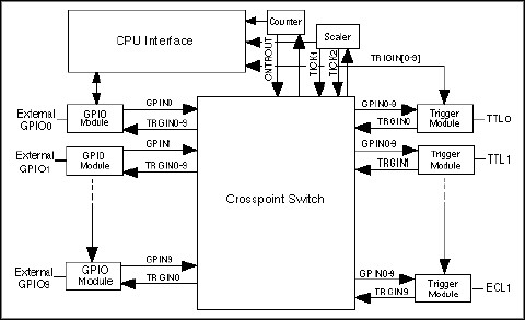
Figure 5, the TIC chip block diagram, shows how the external trigger and external GPIO lines can map to one another. Notice that GPINx and TRGINx are internal signals to the TIC. For now, consider these lines as pathways for connecting the external lines to one another. The functions listed previously are used to program the different modules that make up the TIC chip. How each of these modules is configured is described below. Notice that the terms internal and external are from the point of view of the TIC chip, not the controller.
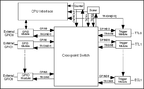
The Crosspoint Switch block is simply a point-to-point switch. It connects each GPIO module to each Trigger module electrically, as well as connecting the counter and timer signals to these modules. When mapping external trigger lines, the function MapTrigToTrig() maps an external trigger line to and from an external GPIO line. It can also map the counter output signals to these external lines. Example 5 shows how to connect TTL0 to GPIO1 (which is connected to Front Panel Out), and GPIO0 (which is connected to Front Panel In) to TTL2.
Example 5 Mapping a Trigger Line to a GPIO Line
controller = -1; /* Local controller */
mode = 0; /* Sync with CLK10 */
SrcTrigger = 0; /* TTL0 */
destTrig = 41; /* GPIO1 = Front Out */
ret = MapTrigToTrig (controller, SrcTrigger, destTrig, mode);
SrcTrigger = 40; /* GPIO0 = Front In */
destTrig = 2; /* TTL2 */
ret = MapTrigToTrig (controller, SrcTrigger, destTrig, mode);
Keep in mind that you cannot map one external trigger line directly to another. As the diagrams of the TIC chip indicate, the crosspoint switch can send the external trigger line to the external GPIO line and vice versa. Therefore, if you want to connect two external trigger lines together, you must use a GPIO module as a wrapback, or short, between the two trigger lines. Example 6 shows how to create the electrical connection between TTL0 and TTL1 by shorting the GPIO module connected to the external GPIO9.
To use a GPIO module as a short for two external trigger lines, use the
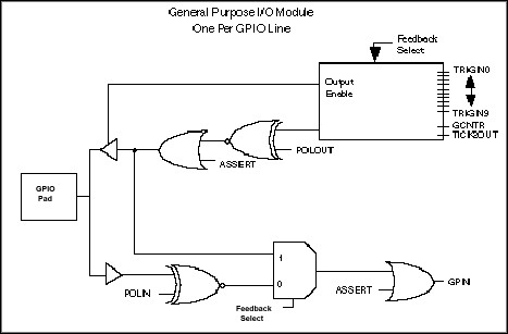
TrigExtConfig() function. It is easiest to think of this function as controlling the GPIO modules inside the TIC chip rather than the GPIO lines. For now consider each GPIO module—there is one module per external GPIO line—as a railroad junction that brings the external GPIO line into the TIC chip (See Figure 6). This railroad junction can do one of three things:
- Propagate the signals out the external GPIO line.
- Bring signals on the external GPIO lines into the TIC chip.
- Disconnect the external GPIO lines from the chip electronically and short the input and output of the GPIO module together.
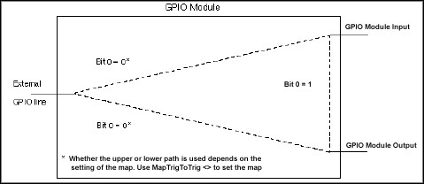 Figure 6. Simplified GPIO Module in the TIC Chip
This last feature makes it possible for you to physically connect trigger lines so that there is no software overhead involved in sending a trigger event from one trigger line to the other. The function uses a mode parameter to control the GPIO modules as shown in Table 1.
Table 1. TrigExtConfig() Mode Parameter Values
| Bit | Configuration Modes |
| 0 | 1: Feed back any line mapped as input into
the crosspoint switch.
0: Drive input to external (GPIO) pin. |
|
|
| 1 | 1: Assert input (regardless of feedback).
0: Leave input unconfigured. |
|
| 2 | 1: If assertion selected, assert low.
0: If assertion selected, assert high. |
|
| 3 | 1: Invert external input (not feedback).
0: Pass external input unchanged. |
Therefore, bit 0 programs the TIC to either short the GPIO module (when bit 0=1) or connect the GPIO module input to the external GPIO line (when bit 0=0). Bit 1 lets you determine whether the GPIO module input is driven by software (when bit 1=1) or by the state of the GPIO module input. Bit 2 is relevant when you assert the line through software (that is, only when bit 1=1) and you use bit 3 when you want the module to bring the signal into the chip from the external GPIO line. The following code uses
TrigExtConfig() to map trigger lines to trigger lines.
Example 6 Mapping a Trigger Line to a Trigger Line
/* This section will allow GPIO9 to be used as a short */
/* circuit between TTL0 and TTL1 by configuring as a */
/* feedback circuit (that is, disconnecting external lines) */
controller = -1; /* Local controller */
extline = 49; /* GPIO9 */
mode = 1; /* Feedback, leave unconfigured */
ret = TrigExtConfig (controller, extline, mode);
/* Now connect TTL0 to GPIO9 and GPIO9 to TTL1 */
mode = 0; /* Sync w/ CLK10 */
SrcTrigger = 0; /* TTL0 */
destTrig = 49; /* GPIO9 */
ret = MapTrigToTrig (controller, SrcTrigger, destTrig, mode);
SrcTrigger = 49; /* GPIO9 */
destTrig = 1; /* TTL1 */
ret = MapTrigToTrig (controller, SrcTrigger, destTrig, mode);
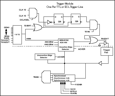
In addition to the GPIO module, the TIC chip has a Trigger module for each external trigger line that can be configured through
TrigAssertConfig(). The external trigger line is connected to the Trigger module and can either drive the Trigger module output or itself be driven by the Trigger module input. However, the internal routing capabilities of the Trigger module differ substantially from the GPIO module.
The Trigger module provides the following capabilities.
- Synchronization with CLK10
- Stretching the incoming pulses on the external trigger lines to a minimum length (pulse-stretching)
- Edge detection and interrupt generation capabilities for monitoring external trigger lines
- Participation in the hardware acknowledge of the SEMI-SYNC protocol
The pulse stretch feature means that the pulse of an external trigger line can be stretched in time before being mapped to another line. This feature can be very important when mapping a trigger line out of the chassis onto a long cable, which would require more settling time than the original pulse could provide, or sending the signal to another device that may not be able to respond to the small assertion times of the VXIbus trigger protocols. The
TrigAssertConfig() function handles the configuration of the pulse-stretch feature, as well as the other features of this module. This function uses a mode parameter similar to the
TrigExtConfig() function. The hardware acknowledge feature for SEMI-SYNC is described in the Understanding the SEMI-SYNC Trigger protocol section later in this document. In addition, refer to Appendix A for a more in-depth description of the Trigger module.
TIC Counter Functions
Inside the TIC chip are three counters: a 16-bit counter and two 5-bit timers. Like the GPIO and Trigger modules discussed above, the counter and scalar modules are more thoroughly described in Appendix A. Please refer to the appendix for more information.
The 16-bit counter can be driven from the CLK10 signal, the EXTCLK signal, or any of the trigger lines on the P2 connector. The counter has two outputs: a 100 ns pulse on each clock edge (TCNTR), and a terminal count assertion (GCNTR). Both of these outputs are available to be mapped inside the crosspoint switch, with TCNTR connected to the Trigger module and GCNTR connected to the GPIO module.
When programming this counter, there are three possible modes that can be selected through
TrigCntrConfig(): initialize, reload, and disable. The first call to the counter must be with the initialization mode. Once the counter has been initialized, a call to either
EnableTrigSense() or
SrcTrig() starts the counter. For example, the following code programs the counter to count for 100 ms (1000 clock pulses from CLK10).
Example 7 Using the 16-Bit Counter to Count from CLK10
controller = -1; /* Local controller */
mode = 0; /* Initialize the counter */
source = 70; /* CLK10 */
count = 1000;
ret = TrigCntrConfig (controller, mode, source, count);
/* Use SrcTrig() to start the counter */
line = 50; /* 16-bit Counter */
prot = 4; /* SYNC, to start */
timeout = 0L; /* No timeout */
ret = SrcTrig (controller, line, prot, timeout);
If the counter is reconfigured with the initialization mode, a call to
EnableTrigSense() or
SrcTrig() is again required to start the count. If the counter is simply reloaded using the reload mode, the counter begins counting immediately upon being reloaded. At any point,
TrigCntrConfig() can be called to abort or disable the counter with the disable mode.
Although it is true that both
EnableTrigSense() and
SrcTrig() can start the counter, they have a different emphasis. Because it is possible to have the trigger lines as the source of the counter clock, it is possible to count trigger assertions. By configuring the counter with the correct count, mapping its inputs and outputs, and starting it with
EnableTrigSense(), the counter can be programmed to count any of the protocols, rather than sourcing them. Example 8 shows sample code for setting the counter to count multiple SYNC trigger assertions.
Example 8 Counting Triggers with the TIC Counter
controller = -1; /* Local controller */
mode = 0; /* Initialize the counter */
source = 0; /* Clock the counter from TTL0 */
count = 10;
ret = TrigCntrConfig (controller, mode, source, count);
/* Use EnableTrigSense() to enable the counter */
line = 50; /* TIC counter */
prot = 4; /* SYNC */
ret = EnableTrigSense (controller, line, prot);
Once the count is complete, GCNTR will assert and you can have the TIC generate an interrupt for your program.
TIC Timer Functions
Besides the 16-bit counter, there are two 5-bit counters, known as the TICK timers, which use the 5-bit value as the power of two for the count. Like the 16-bit counter, the TICK timers also have different modes that they can be configured for. However, the TICK timers differ in that they can be initialized in one of two different modes: rollover or non-rollover. Rollover mode causes the counter to be reloaded automatically at the end of the count without software intervention. Non-rollover mode causes the counters to cease operation when the count is finished.
Example 9 Using the TIC Timers
controller = -1;/* Local controller */
mode = 1; /* Initialize the counter, non-rollover
mode */
source = 70; /* CLK10 */
tcount1 = 3; /* 2 to the 3rd power */
tcount2 = 0; /* Does not matter */
ret = TrigTickConfig (controller, mode, source, tcount1,
tcount2);
line = 60; /* TIC TICK timers */
prot = 4; /* SYNC */
timeout = 0L; /* No timeout */
ret = SrcTrig (controller, line, prot, timeout);
As shown in Example 9, setting the value to 3 causes the TICK timer to count eight input pulses (23) before terminating. Notice that
SrcTrig() is used to start the timer in the same way that it is used by the 16-bit counter. Also, using the
TrigTickConfig() function, you can program the TICKs to count from the CLK10 signal, the EXTCLK input, or any of the external GPIO lines.
The output of the TICK timers is a square wave with a period of the count value in clock pulses. If the counter is set to 3, resulting in a count of eight, the TICK output would be high for four counts and low for four counts. If the timer is clocked from the CLK10 signal with rollover mode, a count of eight would result in an 800 ns period square wave (1.25 MHz). See Example 10.
Example 10 Generating Continuous Square Waves with the TIC Timers
controller = -1;/* Local controller */
mode = 0; /* Initialize the counter, rollover mode */
source = 70; /* CLK10 */
tcount1 = 3; /* 2**3 */
tcount2 = 0; /* Does not matter */
ret = TrigTickConfig (controller, mode, source, tcount1,
tcount2);
line = 60; /* TIC TICK Timers */
prot = 4; /* SYNC */
timeout = 0L; /* No time-out */
ret = SrcTrig (controller, line, prot, timeout);
The TICK timers are integrated in their operation. The first TICK counter, TICK1, actually controls the counter circuitry. When TICK1 completes its count (assuming non-rollover mode), the counter circuitry is disabled, whether or not TICK2 has completed its count. You can use this feature to generate square waves for a specific amount of time by entering the desired
frequency of the square wave in TICK2, and the length of the square wave in TICK1 (with non-rollover mode selected). The resulting TICK2 output is a 50 percent duty cycle square wave up to the last count6. The following code will generate a 400 ns square wave for 51.2 ms out of the TICK2 output.
Example 11 Generating Finite Length Square Waves with the TIC Timers
controller = -1;/* Local controller */
mode = 1; /* TICK1 for non-rollover so it will */
/* end with the end of the count */
source = 70; /* CLK10 */
tcount1 = 10;
tcount2 = 2;
ret = TrigTickConfig (controller, mode, source, tcount1,
tcount2);
line = 60; /* TIC TICK timers */
prot = 4; /* SYNC */
timeout = 0L; /* No timeout */
ret = SrcTrig (controller, line, prot, timeout);
LabVIEW Implementation of NI-VXI
When using LabVIEW, all NI-VXI virtual instruments (VIs) make calls to the main NI-VXI library (DLL, or dynamic link library for Windows; .so, or shared object files for Sun or HP-UX; and the Device Manager on Macintosh). Because of this, there is a LabVIEW VI for every NI-VXI function discussed so far. LabVIEW differs from the NI-VXI trigger functions only in how to deal with interrupts. LabVIEW has two approaches for installing a user-written interrupt handler.
The first approach is to use the
PollTrigHandler()
7 VI, which waits until a trigger interrupt has occurred and then continues. This is similar to the
WaitForTrig() function, but differs mainly in the return information provided. This return information for
PollTrigHandler() is the same as an interrupt handler would receive.
The second approach in LabVIEW is to use the LabVIEW feature of occurrences. An occurrence is a tool that can block execution at multiple points in a LabVIEW program until a certain event occurs. Using this, you can pause different execution flows until an interrupt occurs. Using the
SetTrigHandler VI, you can tell LabVIEW to generate an occurrence when a trigger interrupt occurs. Please refer to the LabVIEW documentation for more information on occurrences.
LabWindows/CVI Implementation of NI-VXI
LabWindows/CVI is a complete, full-function C programming environment for PC-compatible computers running Windows and for Sun SPARCstations. Because LabWindows/CVI calls NI-VXI directly, you do not have to account for any compatibility issues. You can use all the NI-VXI functions designed for C platforms without alteration in the LabWindows/CVI environment.
GPIB-VXI Implementation of NI-VXI
The GPIB-VXI models, including the /C and /CP models, have the capability to control and respond to triggers. Although there are no GPIB commands equivalent to the VXIbus trigger capability, the GPIB-VXI from National Instruments does come with its own local command set that you can use to program for a wide variety of VXIbus features, including triggering. In addition, the /C and /CP models have the TIC chip onboard. The local command set is simply a set of string commands that the GPIB-VXI parses and executes. Example 12 shows the NI-VXI command to source TTL0 with the SYNC protocol (in C).
Example 12 Using the GPIB-VXI Local Command Set for Triggering
ret = SrcTrig (-1, 0, 4, 0L);
whereas using IEEE 488.2 commands on a GPIB-VXI, it would look like
Send (boardID, GPIBAddress, "SrcTrig 0, 4, 0", NLend);
and the IEEE 488.1 command would be,
ibwrt (deviceID, "SrcTrig 0, 4, 0", 15);
The local command set is functionally equivalent to the NI-VXI API, and in most cases the functions themselves are identical. The names of the API may differ occasionally due to differences in the abbreviations; for example,
AcknowledgeTrig() becomes
AckTrig. But the parameter lists for the functions are the same except that the GPIB-VXI does not need the
controller parameter used by the NI-VXI API.
The GPIB-VXI controller also has an extra command for use with the SRQ line in the GPIB cable. The local command
TrigToREQT causes the SRQ line to be asserted if a specified TTL trigger, ECL trigger, or counter output becomes asserted. Not only does the GPIB-VXI assert the SRQ line and respond to the serial poll, but you can also use
TrigToREQT to specify which logical address should be credited with asserting the SRQ. As a result, you can have multiple devices asserting triggers, and hence SRQ, and have the serial poll information returned to indicate the source of the trigger.
