NI does not actively maintain this document.
This content provides support for older products and technology, so you may notice outdated links or obsolete information about operating systems or other relevant products.
The NI 6533 Family devices have control lines that dictate when data transfers occur, and these control lines carry digital TTL (transistor-transistor logic) level signals that indicate when one device is ready to send data and the other is ready to receive the data. Handshaking devices use the Acknowledge (ACK) and Request (REQ) control lines to coordinate digital data transfers between the two devices. The input device uses a control line to signal that it is ready to receive new data. The output device uses the other control line to indicate that new data is available on the data lines. The timing of the ACK signal that is sent to the peripheral device and of the REQ signal that is expected from the peripheral device is determined by a handshaking protocol. Handshaking protocols define how a buffer of digital data is transferred between two devices. Data transfer occurs only when both devices signal that they are prepared to provide or accept new data.
Note: To learn about handshaking protocols and the corresponding behavior for the control lines, refer to Digital I/O Applications.
Measurement Studio supports both asynchronous and synchronous handshaking. In asynchronous handshaking, each device controls one control line that it uses to inform the other device that it is ready for data transfer. The exact protocol you select determines the timing of the control lines. Measurement Studio includes the following asynchronous handshaking protocols: Level, Edge (including Leading Edge, Trailing Edge, and Long Pulse), and 8255 emulation.
Note: Check the documentation for your peripheral devices to determine which protocols are valid.
Each mode specifies the conditions for a single data value to be transferred between two devices. The control lines must change state and be reactivated before additional data can be transferred.
Synchronous handshaking uses three control lines for data transfer -- one control line from each device and one shared clock line. Use synchronous or clocked protocol to achieve a higher data transfer rate. The NI 6533 Family devices perform synchronous data transfer through the burst mode protocol. In burst mode, the ACK and REQ lines are used in addition to a shared clock (named PCLK) that one of the devices controls. When both the ACK and REQ signals are active, data transfer occurs on each rising edge of the PCLK signal. Either device can pause the data transfer by de-asserting its control line. Transfer is sustained at the frequency of the clock signal when both lines are asserted.
See Also:
Digitial I/O Applications
Pattern I/O transfers data at a predetermined frequency. It is not a handshaking mode, but rather a method of transferring digital data at a predetermined frequency without control lines. You can use pattern I/O to perform both input and output operations. The frequency at which data is transferred is determined by the signal connected to the REQ line. This timing signal can be generated externally or the DAQ device can generate its own internal REQ pulse. When the DAQ device generates internal requests, the request pulse is present on the REQ line by default.
Tip: Use pattern I/O only with devices that can sustain the data transfer rate.
Measurement Studio offers two controls for handshaking and pattern I/O. Use the Measurement Studio Digital Input (CWDI) ActiveX control to perform buffered handshaking and pattern input operations, and the Measurement Studio Digital Output (CWDO) ActiveX control to perform buffered handshaking and pattern output operations.
|
| Begin by placing either the CWDI or CWDO control on the user interface form. Use the CWDI control for digital input operations and the CWDO control for digital output operations. Right click on the control and select Properties. This section explains how to use the property pages to configure the controls for handshaking and pattern I/O. The rest of this application note uses examples to demonstrate how to control digital data transfers programmatically. |
Configuring Your Device and Digital Operation
Use the General property page to select a digital device, the ports for the data transfer, and the buffer size and duration (continuous or finite) of the data transfer, as shown in Figure 1. The configuration in Figure 1 sets a CWDI control to input a continuous buffer of data through ports 0 and 1 on a PCI-DIO-32HS board.
Note Make sure your device can perform buffered digital data transfers
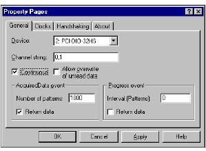
Use the Channel string property to specify the group (or list of ports) involved in the data transfer. In this example, the CWDI control is retrieving data from ports 0 and 1. You can specify multiple ports with a comma-delimited list.
Note: Search for ChannelString in the Measurement Studio Reference for information about which ports can be used for buffered digital I/O.
Continuous indicates that the data will be transferred in a buffer and Measurement Studio will continue reading or writing data until the Reset method is called or an error occurs.
The Number of patterns property specifies the number of patterns per port that are stored in the buffer. For two or more port operations, the buffer size is calculated as (Number of patterns)* (number of ports specified in Channel string). For example, if Number of patterns is 1000 and there are two ports, the buffer contains a total of 2000 patterns.
According to the configuration shown in Figure 1, as soon as the buffer contains the requested number of patterns, the AcquiredData event is generated and the whole buffer of data is returned to the event. Alternatively, you can use the Progress event with the CWDI or CWDO control to return an intermediate number of patterns that have been transferred from or written to the buffer.
When you are reading from two or more ports, keep in mind that data is interleaved by port. For example, if you want to process data from only one port in a two-port operation, extract one item, skip the next, extract the next, and so on.
If you are writing data to two or more ports, you must interleave the data by port. For example, imagine that you are generating 100 patterns of data for ports 0 and 1 in an array named Waveform. Waveform needs to be an array of 200 points. During the first update, Waveform(0) is written to port 0 and Waveform(1) is written to port 1. During the next update, Waveform(2) is written to port 0 and Waveform(3) is written to port 1, and so on.
Setting Handshaking Properties
Use the Handshaking property page to set the handshaking mode and properties for timing and behavior of the control lines. For example, Figure 2 sets handshaking properties for leading-edge handshaking with a 100 ns delay in the Acknowledge pulse.
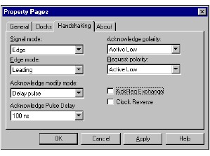
Note: You don’t need to set any properties on this page if you are using pattern I/O.
The following list describes the handshaking properties you need to set on this property page:
|
Protocol
|
Edge mode
|
Acknowledge modify mode
|
| Leading Edge | Leading | Delay pulse or No modification |
| Trailing Edge | Trailing | Delay pulse or No modification |
| Long Pulse | Leading or Trailing | Change duration |
The following code example demonstrates how to configure a burst mode input operation using an external PCLK signal. Before you run this example, connect the clock source to PCLK1 (pin 5 on the 32HS connector). Connect the control line from the external device to REQ1 (pin 2). Connect ACK1 to the external device. To simulate an external device, you can set REQ1 to active low. REQ1 is always asserted and ready for data transfer.
CWDI1.Device = 1
CWDI1.ChannelString = "0:1"
'Number of patterns
CWDI1.NPatterns = 1000
'Generate AcquiredData event to return data
CWDI1.AcquiredDataReturnData = True
'Set handshaking properties
CWDI1.UpdateClock.ClockSourceType = cwdioCSIOConnector
CWDI1.Handshake.SignalMode = cwdioSignalBurst
CWDI1.Handshake.AcknowledgePolarity = cwdioActiveHigh
CWDI1.Handshake.RequestPolarity = cwdioActiveLow
'Set the PCLK to an external source
CWDI1.Handshake.ClockReverse = True
'To use an internal PCLK, you would need to modify
'the example as follows:
'CWDI1.Handshake.ClockReverse = False
'CWDI1.Handshake.PCLKFrequency = cwdioPCLK_10MHz
CWDI1.Configure
CWDI1.Start
After the buffer contains 2000 patterns (1000 from port 0 and 1000 from port 1), the AcquiredData event is generated and the data is returned. From the AcquiredData event, you can display the data in a Measurement Studio CWGraph ActiveX control, analyze it, or save it to a file.
Setting Pattern Generation Properties
The update clock controls when data is transferred. For most handshaking operations, you’ll set the clock source type to I/O connection because data transfer is usually driven by the ACK and REQ lines on the I/O connector. However, you can route the ACK and REQ signals from another device across the RTSI bus. Pattern I/O can use the internal clock or receive an external clock signal on the REQ line or across the RTSI bus from another device.
For pattern I/O, use an internal clock source and specify the clock settings either in terms of scans/second or seconds/scan or specify a frequency and divisor for the internal clock. Figure 3 shows how you might configure pattern output with an internal clock at 500,000 scans/second.
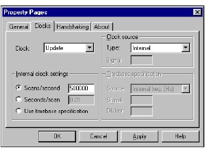
If you use an external clock for pattern I/O, connect the clock source to the REQ input on the I/O connector or route it to the REQ input through a RTSI line.
This example shows you how to set up a pattern output operation programmatically. You do not need to set any properties on the Handshaking tab or on the Handshake object for pattern I/O. To generate data at a specified rate, select an internal clock frequency:
CWDO1.Device = 1
CWDO1.ChannelString = "0:1"
'Number of patterns
CWDO1.NPatterns = 2500
'Generate Progress event each time half the
'buffer is written
CWDO1.ProgressInterval = CWDO1.NPatterns / 2
CWDO1.Continuous = False
CWDO1.UpdateClock.ClockSourceType = cwdioCSInternalClock
CWDO1.UpdateClock.Frequency = 1000
CWDO1.Configure
'wfm contains interleaved data patterns
'One routine that can be used to build these data patterns is BuildDIOData().
CWDO1.Write wfm
CWDO1.Start
You can modify the example to perform continuous generation of the same digital patterns. The following code configures the CWDO control to output the entire buffer and continuously loop back to the first point in the buffer and output it again:
CWDO1.Continuous = True
CWDO1.AllowRegeneration = True
Now that the generation is continuous, you can use the Progress event to supply new waveform data to the buffer. The Progress event is generated when the number of patterns specified by ProgressInterval has been written out. Use the Progress event to notify your program that a portion of the data buffer (equal to ProgressInterval) has been generated and needs to be updated, as in the following example:
Private Sub CWDO1_Progress(PatternCount As Variant)
Dim wfm
'Write new data to the buffer. wfm contains interleaved data patterns.
'One routine that can be used to build these data patterns is BuildDIOData().
'For example, wfm = BuildDIOData(CWDO1.NPatterns / 2, CWDO1.NPorts)
CWDO1.Write wfm
‘Display the data on a graph
PlotIndividualDigitalLines_CWGraph1, wfm
End Sub
Tip: This example uses the PlotIndividualDigitalLines subroutine. This subroutine displays the data from each digital line as a separate plot.
If you want to test your DAQ system before connecting it to external devices, you can connect two DAQ devices over the RTSI bus. When handshaking data between NI 6533 devices, you want the ACK signal from each device connected to the REQ signal of the other. If you use a standard SH6868-D1 cable to cable the two devices together, they are by default connected ACK to ACK and REQ to REQ. To make the correct ACK to REQ connections, set AckReqExchange to True for one device, and than program the remaining handshaking properties as normal.
Alternatively, it might be more convenient to route the REQ, ACK, and PCLK signals over the RTSI bus rather than wiring the signals into the I/O connector when working with multiple NI 6533 devices in the same computer. To make these signals available on the RTSI bus, set ClockSourceType to cwdioCSRTSI and call the RouteRTSI method on the CWDAQTools control for each signal, as in the following example:
'Set update clock to a RTSI connection
CWDO1.UpdateClock.ClockSourceType = cwdioCSRTSI
'Configure REQ1(signal 0) to be received on
'RTSI trigger line 0
CWDAQTools1.RouteRTSI deviceNum, cwRouteRTSIControlConnect, _
0, 0, cwRouteRTSIDirBoardReceive, map
'Configure ACK1(signal 2) to be transmitted on RTSI
'trigger line 1
CWDAQTools1.RouteRTSI deviceNum, cwRouteRTSIControlConnect, _
2, 1, cwRouteRTSIDirBoardTransmit, map
Note The Measurement Studio DAQTools (CWDAQTools) ActiveX control provides utility functions for the DAQ controls. The RouteRTSI method has the following prototype:
The following example shows how to configure the second device to receive the REQ signal on line 1 and to send the ACK signal on line 0. When the application completes, call RouteRTSI to disconnect the signals from all four trigger lines.
'Configure REQ1(signal 0) to be received on RTSI
'trigger line 1
CWDAQTools1.RouteRTSI deviceNum, cwRouteRTSIControlConnect, _
0, 1, cwRouteRTSIDirBoardReceive, map
'Configure ACK1(signal 2) to be transmitted on RTSI
'trigger line 0
CWDAQTools1.RouteRTSI deviceNum, cwRouteRTSIControlConnect, _
2, 0, cwRouteRTSIDirBoardTransmit, map
The following table lists the signals that might be available on the RTSI line for NI 6533 Family devices.
|
Signal Name
|
Signal Direction
|
Signal Code
|
Signal Description
|
|
REQ1
|
Bidirectional
|
0
| Group 1 Request Line. In handshaking mode, a group’s REQ line carries handshaking status information from the peripheral device; in pattern I/O mode, a clock. |
|
REQ2
|
Bidirectional
|
1
| Group 2 Request Line. In handshaking mode, a group’s REQ line carries handshaking status information from the peripheral device; in pattern I/O mode, a clock. |
|
ACK1
|
Bidirectional
|
2
| Group 1 Acknowledge Line. In handshaking mode, a group’s ACK line carries handshaking control information to the peripheral device. |
|
ACK2
|
Bidirectional
|
3
| Group 2 Acknowledge Line. In handshaking mode, a group’s ACK line carries handshaking control information to the peripheral device. |
|
PCLK1
|
Bidirectional
|
4
| Group 1 Peripheral Clock Line. In burst mode only, these lines carry clock signals to or from the peripheral device. |
|
PCLK 2
|
Bidirectional
|
5
| Group 2 Peripheral Clock Line. In burst mode only, these lines carry clock signals to or from the peripheral device. |
|
STOPTRIG1
|
Receiver
|
6
| Group 1 stop trigger. Currently not available with Measurement Studio. |
|
STOPTRIG 2
|
Receiver
|
7
| Group 2 stop trigger. Currently not available with Measurement Studio. |