NI does not actively maintain this document.
This content provides support for older products and technology, so you may notice outdated links or obsolete information about operating systems or other relevant products.
 |
|
Instrument
|
Connections
| |
| DMM | ||

| DC/AC Voltmeter DC/AC Ammeter Ohmmeter Capacitance meter Inductance meter Diode tester Audible continuity testing | VOLTAGE HI and VOLTAGE LO, ±20 VDC CURRENT HI and CURRENT LO, 250 mA maximum CURRENT HI and CURRENT LO, 5 Ω to 3 MΩ CURRENT HI and CURRENT LO, nonpolar or biased for electrolytic, 50 pF to 500 µF CURRENT HI and CURRENT LO, 100 µH to 100 mH CURRENT HI and CURRENT LO Measured across CURRENT HI and CURRENT LO |
| Note: Resistance, Inductance, and Capacitance measurements function generator is in Manual mode Caution: By connecting different signals to the DMM terminals on the prototyping board and the DMM connectors on the control panel, you are shorting them together, potentially damaging the circuit on the prototyping boards. | ||
| Oscilloscope | ||
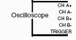
| Channel A Channel B Digital Trigger Analog Trigger | CH A+ and CH A- CH B+ and CH B- Connect TTL-level signal to TRIGGER Configure the trigger level and slope for channel A or B |
| Caution: By connecting different signals to the Scope terminals on the prototyping board and the Scope connectors on the control panel, you are shorting them together, potentially damaging the circuit on the prototyping board. | ||
| Function Generator | ||
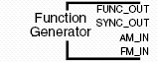
| Signal Output TTL-Compatible Clock Signal Amplitude Modulation Frequency Modulation | FUNC_OUT SYNC_OUT AM_IN FM_IN |
| Digital Reader and Writer | ||
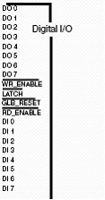
| Digital Input Digital Output |
DI0-7
DO0-7 |
| Bode Analyzer | ||
| Stimulus signal connections Output connections | Connect FUNC_OUT to positive input of circuit and ACH1+. Connect GROUND to the reference point on the circuit and to ACH1- Connect output of circuit to ACH0+ and connect ACH0- to GROUND |
| Impedance Analyzer | ||

| Passive component + Passive component - | CURRENT HI CURRENT LO |
| Two-Wire Analyzer | ||

| Terminal 1 Terminal 2 | CURRENT HI CURRENT LO |
| Three-Wire Analyzer | ||
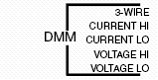
| Collector Base Emitter | 3-WIRE CURRENT HI CURRENT LO |
| Arbitrary Function Generator | ||
|
| Function output | DAC0 or DAC1 |
| Variable Power Supply | ||
|
| 0 to +12 V -12 to 0 V | SUPPLY + SUPPLY - |
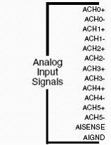
NI ELVIS does not support floating measurements. Therefore, because the analog channels are differential, you must establish a ground point somewhere in the signal path. As long as the signal you are measuring is referenced to one of the NI ELVIS GROUND pins, the measurement is correctly referenced. If a floating source, such as a battery, is being measured, be sure to connect one end of the signal to the NI ELVIS GROUND. Terminals for the NI ELVIS GROUND signal are located at several locations on the prototyping board. All of these signals are connected together.