ECU Virtualization: The Journey
Overview
To adeptly replicate Electronic Control Unit (ECU) behavior, you need a powerful tool for automotive development and testing. A recommended methodology for virtualizing ECUs in vehicles relies on a systematic process, emphasizing the benefits of early testing through adherence to the four layers of the Classic AUTomotive Open System ARchitecture (AUTOSAR) architecture, spanning from application to microcontroller abstraction. This white paper outlines crucial steps, including application modeling and virtual ECU (vECU) simulation using NI VeriStand and Synopsys’ Silver software.
Contents
- Critical Areas of Focus for the Virtualization of ECUs in Vehicles
- Achieve a Real-Time Vehicle ECU Simulation
- Next Steps
- References
Critical Areas of Focus for the Virtualization of ECUs in Vehicles
Most ECUs adhere to a well-defined architecture (See Figure 1) established by AUTOSAR, which is a standardized software architecture developed collaboratively by automotive manufacturers, suppliers, and other stakeholders. It provides a common platform for the development, integration, and management of software in modern vehicles. AUTOSAR aims to address the increasing complexity of automotive electronic systems by defining a standardized framework for software architecture, application interfaces, and communication protocols.
This open and standardized approach allows different automotive software components from various suppliers to work seamlessly together, fostering interoperability and scalability. AUTOSAR promotes reusability of software modules, making it easier for automotive companies to develop and maintain software across different vehicle models and electronic control units. This results in more efficient development processes, shortened time to market, and improved overall system reliability in the automotive industry.
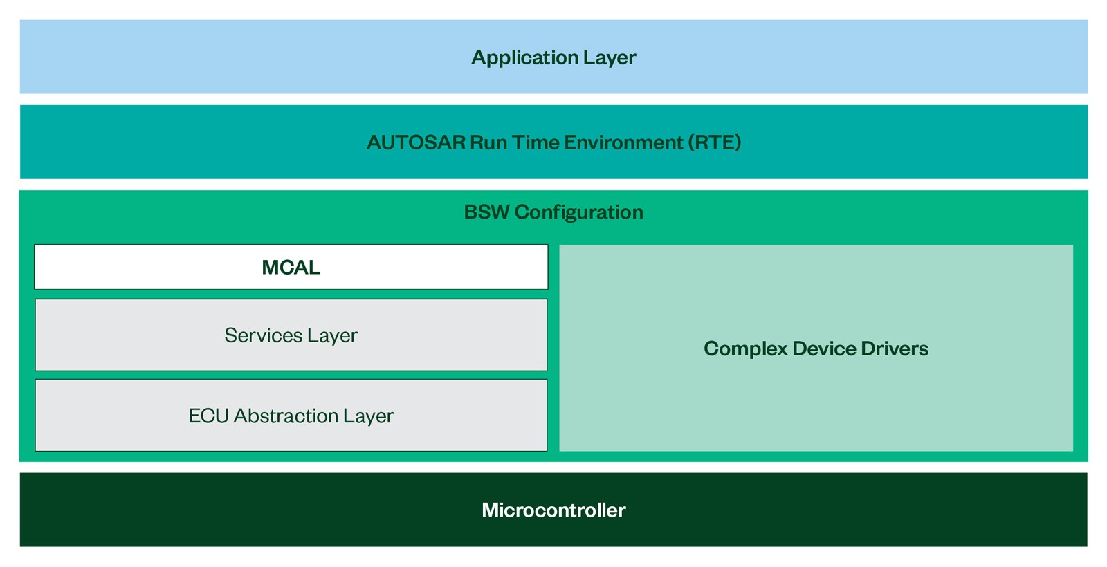
Figure 1: AUTOSAR ECU Layered Architecture
As depicted in Figure 1, the AUTOSAR architecture consists of four layers endowing an ECU with capabilities. Leveraging this architecture in ECU simulation facilitates the early validation of features, eliminating the necessity to wait for the physical ECU, thus expediting the testing process.
To gain a better understanding of the purpose behind each layer, let’s delve into the ultimate tasks of each one of the four layers of the AUTOSAR Classic platform architecture.
- Application Layer:
- Implements top-level application code.
- Organizes software components (SWCs) for distinctive features as needed.
- Implements standardized interfaces associated with SWCs to develop automotive applications.
- Facilitates communication between components through well-defined ports, enabling interaction with the AUTOSAR Basic Software layer.
- Triggers cyclic or event-based execution of the actual implementation within SWCs, involving runnable entities such as data reception.
- Run-Time Environment Layer:
- Acts as the middleware layer.
- Provides communication services for AUTOSAR SWCs and applications with AUTOSAR sensor/actuator parts.
- Makes SWCs independent of specific ECU mappings.
- Features specialization for each ECU and application.
- Ensures autonomy for AUTOSAR software components, fostering flexibility and portability.
- Basic Software (BSW) Configuration Layer:
- ECU Abstraction Layer:
- Interfaces with Microcontroller Abstraction Layer (MCAL) for peripheral access.
- Establishes an API for Micro Controller Unit (MCU) interaction, ensuring independence from ECU hardware.
- Achieves mounting independence from MCU while relying on ECU hardware.
- Complex Drivers:
- Handles complex functions (for example, injection control).
- Directly accesses the MCU to meet special timing requirements.
- Mounts a standardized interface as per AUTOSAR.
- Microcontroller Abstraction Layer:
- Directly accesses on-chip MCU peripherals and external devices.
- Ensures upper software independence from MCU specifics.
- Establishes an interface that remains unaffected by standardized MCU specifications.
- ECU Abstraction Layer:
- Microcontroller Layer:
- Serves as the interface enabling communication between software layers and microcontroller hardware peripherals.
In a more detailed exploration of these layers, it becomes evident that the application layer plays a pivotal role by encapsulating the core functionality of the ECU. Leveraging the code within this layer, we can accurately simulate our vECU.
Achieve a Real-Time Vehicle ECU Simulation
To achieve accurate simulation of a vECU, a structured approach is essential (see Figure 2). Therefore, carrying out the following key steps, we can achieve our objective.
- Application Modeling: Begin by creating a comprehensive model that faithfully represents the ECU’s capabilities using MathWorks® MATLAB® software and Simulink® software.
- Application Authoring: Establish a meticulous mapping of the diverse I/O signals present in the ECU to AUTOSAR components. This mapping can be accomplished through tools like MATLAB software, Simulink software, or ISOLAR-A*.
- Basic Software Configuration: Replicate the essential basic software components that govern ECU operation. This task can be accomplished with the assistance of ISOLAR-B*.
- Virtual ECU Building: Start the process of virtualizing the ECU using a configuration file with the Synopsys Software, known as Silver.
- Virtual ECU Simulation: Use NI VeriStand software, combined with the NI-Aliaro HIL real-time test platform, which creates an effective simulation given the reconfigurability of its I/O ports according to the desired signal type. This capability empowers us to simulate the vECU in alignment with precise customer specifications. The seamless transition between various vECUs is achieved with the click of a button allowing users to jump among simulated ECUs.
* ISOLAR-A and ISOLAR-B refer to software tools by ETAS for developing embedded software in automotive ECUs. They aid in creating AUTOSAR-compliant software, standardizing architectures for improved scalability and interoperability. For the latest details, consult ETAS official documentation or contact them directly.
The visual representation below summarizes the recommended process for ECU virtualization. To guide you through each step, we have highlighted NI’s recommended tools in bold. Additionally, each step lists other widely used tools that can be considered for the respective processes. This structured approach aims to enhance clarity and assist in making informed decisions when implementing ECU virtualization.
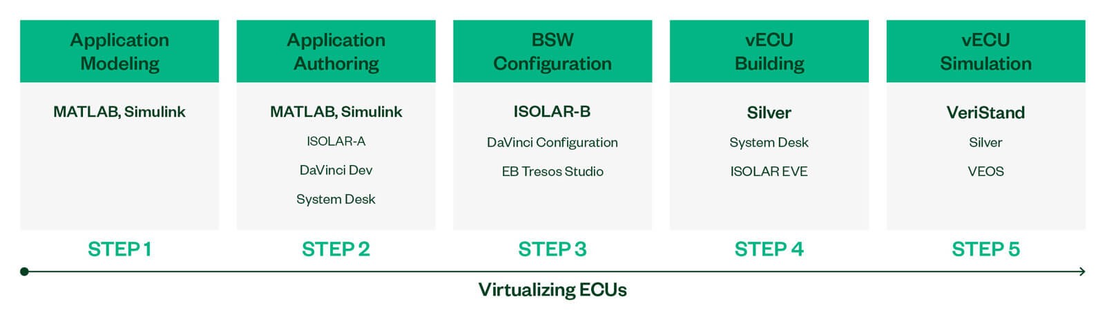
Figure 2: Virtual Validation Process
Therefore, by following these well-defined steps, we can effectively and efficiently simulate any vehicle ECU behavior, offering a powerful tool for automotive development and testing, saving time, and shifting left in the testing process.