Using Vision RIO to Synchronize Vision and I/O with Queued Pulses
Overview
Contents
- Triggered Acquisition with Encoder-Controlled Ejector Station
- Triggered Acquisition with Proximity-Controlled Ejector Station
- Triggered Acquisition with Multiple Encoder-Controlled Ejectors
- Multiple Ejectors Controlled with PLC Issued Time Stamps
Triggered Acquisition with Encoder-Controlled Ejector Station
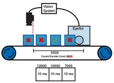
A common inspection scenario involves parts moving along a path with a known distance between the acquisition location and ejector location. The Vision RIO FPGA latches the encoder count when the camera is triggered. If the part fails the inspection, the vision system adds an offset that accounts for the travel distance between the camera trigger and the ejector trigger. The FPGA uses a queue to keep track of the line to drive, the trigger condition, and the duration of the pulse. In this example, a pulse of 10 ms is added to the queue for every failed part. Each queued pulse is triggered at the configured encoder count, ejecting the failed parts.
In this scenario, a pulse is only added to the queue when a failed part is detected. Since the ejector is triggered by an encoder count, the good parts may pass by while the ejector waits for the encoder count to match the next failed part.
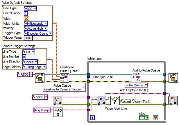
An example VI that implements this inspection scenario is pictured below:
In this example, ISO Output 0 is configured as the output line to generate the pulse on with a trigger value of 5000 encoder counts relative to when the camera was triggered. TTL 0 is configured as the input line to monitor for the camera trigger’s rising edge. The Vision Algorithm will return a False for the Passed Vision Test result if the part fails, and this result will add a 10 ms pulse to the queue. When the Add Pulse to Queue VI is called inside the While Loop, it will retrieve the latched encoder count that corresponds to when the camera was triggered, add 5000 to this value, and add this relative pulse item to the queue. If the Passed Vision Test is True, an Empty Pulse, or 0 ms pulse, will be added to the queue so the part will not be ejected. When using a relative queue, it’s important to always call Add to Pulse Queue for every part because this will always remove the latched encoder count regardless of the Add Empty Pulse flag, and this will ensure the queue of latched encoder counts always corresponds with the correct part.
Triggered Acquisition with Proximity-Controlled Ejector Station
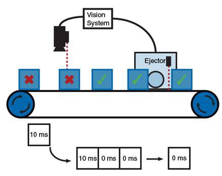
In many situations, the distance between inspected parts moving along a path cannot be guaranteed, as parts may shift as they travel along the path. This prevents an ejector station from being triggered at a specific encoder count. In this case, a proximity sensor near the ejector triggers the queue to drive the next pulse. Unlike the previous example, the queue is triggered even in the presence of a good part. To leave good parts on the line, a 0 ms pulse is added to the queue for every good part, allowing the queue to trigger without driving the ejector.
For example, if 5 parts are inspected and the last 2 parts fail, 5 pulses will be added to the queue. For each acceptable part that is inspected, a 0 ms pulse will be added to the queue. For each failed part, a pulse of 5 ms is added to the queue. As the first of the 5 parts passes a proximity sensor near the ejector, the first pulse in the queue is triggered, driving the 0-width pulse to the ejector and leaving the accepted part on the line. This repeats for the next two acceptable parts. When the first failed part reaches the proximity sensor, the next pulse in the queue is triggered, and the 10 ms pulse ejects the failed part. This is repeated for the second failed part.
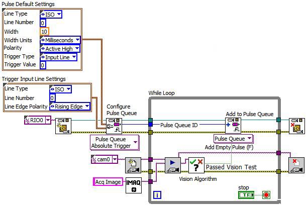
An example VI that implements this inspection scenario is pictured below:
In this example, ISO Output 0 is configured as the output line to generate the pulse on, with a trigger line used to trigger the pulses. ISO Input 0 is configured as the input trigger line to monitor for the proximity sensor signal. The Vision Algorithm will return a False for the Passed Vision Test result if the part fails, and this result will add a 10 ms pulse to the queue. If the result is True, an Empty Pulse, or 0 ms pulse, will be added to the queue.
Triggered Acquisition with Multiple Encoder-Controlled Ejectors
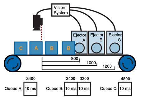
A scenario similar to the fist example involves a sorting procedure. In this scenario, the user must configure a unique pulse queue for each ejector, as parts of a specific type will be ejected at a different location. As in the first example, this scenario latches the encoder count at the time of the camera trigger. The inspection identifies the type of part, adds an offset to the encoder count that accounts for the travel time to the correct ejector, and queues a pulse on the corresponding ejector line. The FPGA will drive the next pulse in the queue when the encoder count matches the count configured as the trigger.
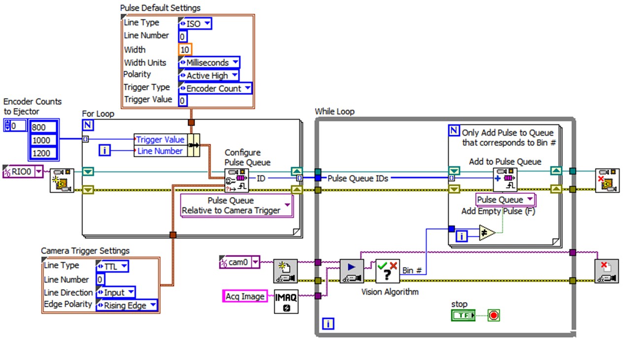
An example VI that implements this inspection scenario is pictured below:
In this example, the ISO Output line is different for each iteration of the For Loop, so each configured Pulse Queue will output on a different ISO Output Line Number. The Trigger Value is also different for each configured pulse queue. All of the configured pulse queues will use the same Camera Trigger Settings since there is just one camera, so all of their encoder count triggers will be relative to the same trigger. The Configure Pulse Queue VI outputs a Pulse Queue ID that identifies the configured queue and this ID will be used to add pulses to the correct bin’s ejector. The Vision Algorithm will return a Bin # that determines which bin the part should be ejected into. All configured pulse queues need to be called with Add to Pulse Queue to ensure the latched encoder count that each queue maintains stays in sync with the current part. Only the Pulse Queue ID that is associated with the Bin # to eject the part into will have the Add Empty Pulse set to False and will use the configured offset to eject the part. All other pulse queues will have an empty pulse added to them and this will ensure their latched encoder values get updated to correspond to the same parts.
Multiple Ejectors Controlled with PLC Issued Time Stamps
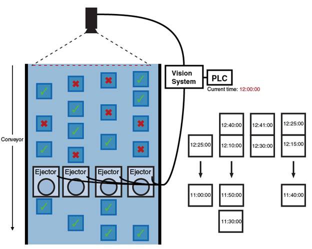
Queued pulses may also be configured to trigger at a specified time stamp. In this scenario, a linescan camera identifies failed parts as they travel in multiple rows down a path towards a row of multiple ejectors. A unique pulse queue is configured for each ejector. A PLC latches the timestamp when the presence of a failed part is detected, and calculates a timestamp that accounts for the travel time to the ejectors. The PLC tells the vision system the calculated timestamp. The vision system then queues a pulse, with the trigger set to the calculated timestamp. The FPGA will then drive the queued pulse when the trigger timestamp occurs.
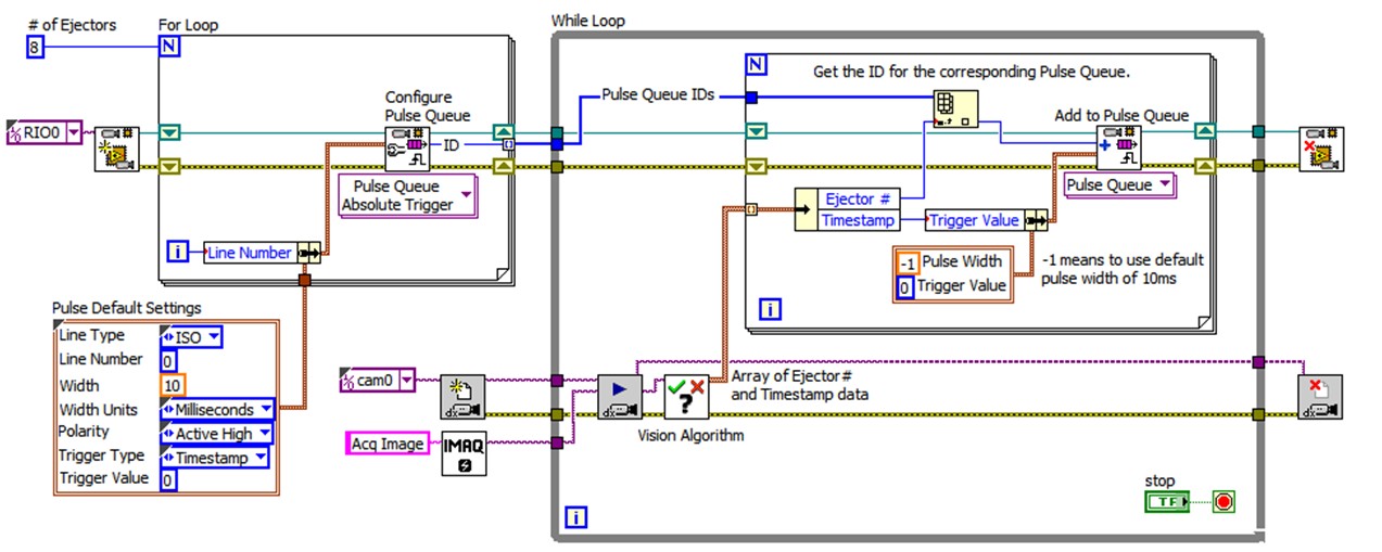
An example VI that implements this inspection scenario is pictured below:
In this example, the ISO Output line is different for each iteration of the For Loop, so each configured Pulse Queue will output on a different ISO Output Line Number. All of the configured pulse queues will use a timestamp as their Trigger Type. The Vision Algorithm will return an array of Ejector # and Timestamp data where the Ejector # determines which ejector to add the pulse to, and the Timestamp defines the Trigger Value for when the pulse should occur. Based on the Ejector #, the correct Pulse Queue ID will be selected and that pulse queue will get an item added to it at the specified timestamp.
