GPIB Messages
Overview
Contents
- Controllers, Talkers, and Listeners
- Command Messages vs. Data Messages
- The GPIB Addressing Protocol
- Multiline Interface Message Table
- Command Message Shortcuts
- Board-Level vs. Device-Level Functions
Controllers, Talkers, and Listeners
- Controllers govern the flow of information on the bus by issuing Talker and Listener assignments to other devices on the bus. They respond to service requests from instruments, and they can pass control of the bus to other Controllers. There can be only one Controller-In-Charge (CIC or System Controller) per bus, which is responsible for overall management of the bus.
- Talkers place information on the data lines of the bus, but only when a Controller instructs them to do so. Only one device can talk at a time.
- Listeners retrieve information from the data lines of the bus, but only when a Controller instructs them to do so. Any number of devices can listen at the same time.
Command Messages vs. Data Messages
The major difference between a command message and a data message is the state of the Attention (ATN) line, which is one of the bus management lines. If the ATN line is asserted, any messages sent on the data lines are heard by all devices, and they are understood to be command messages. If the ATN line is not asserted, only the devices that were addressed to listen may receive the messages on the data lines.
The GPIB Addressing Protocol
The GPIB has eight data lines, which are used to send information one byte (8 bits) at a time. Command messages use seven of the eight bits, as shown in Figure 1, below:
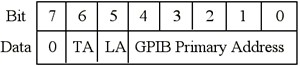
Figure 1. GPIB Addressing Protocol
Bits 0 through 4 indicate the primary address of the device, for which the Talker/Listener assignment is intended. If bit 5 is high, the device should listen. If bit 6 is high, the device should talk. Bit 7 is a "don't care" bit. Its value is ignored, so it is interpreted as a value of zero in command messages.
Each device on the bus must have a unique address. This address consists of a primary address (PAD) and a secondary address (SAD). As you can see from Figure 1, five of the data lines are used to indicate the GPIB primary address. This means that you could have a value from 0 to 31, for a total of 32 (2 to the power of 5) addresses; however, PAD 31 is never used as a primary address, because it is used for special command messages. This leaves a total of 31 possible primary addresses. The Controller-In-Charge (CIC) for a bus is almost always at PAD 0, so the instruments on a bus can have primary addresses from 1 to 30. A common mistake in working with the GPIB is assigning the same address to the controller board and the instrument, which will result in an EADR error (addressing error).
The GPIB secondary address is identical in its range of 0 to 30, which allows for a total of 961 (31 x 31) possible GPIB addresses, but the secondary address is very rarely used (the SAD is typically set to zero). Talker/Listener assignments are part of the primary addressing information, so with PADs you use either bit 6 or bit 5 when you send a command message. This might prompt you to ask, "How do I send the SAD information?" For secondary addresses, you set both bits 6 and 5 high when you send a command message. If you need to communicate with a device that has a secondary address, you need to indicate its primary address first and then immediately indicate its secondary address.
The easiest way to play around with primary and secondary addressing, command messages, and data messages is to use the Interactive Control (IBIC). For example, if you have a board at PAD 0 and an instrument with PAD 2 and SAD 4, and you want the board to talk and the instrument to listen, you would send the following command message in IBIC:
ibcmd "\x40\x22\x64"
The \x40 stands for hex 40, which represents the binary pattern of 0 1 0 0 0 0 0 0. This means that bit 6 is high (talk) and the primary address is zero. The \x22 stands for hex 22, which represents the binary pattern of 0 0 1 0 0 0 1 0. This means that bit 5 is high (listen) and the primary address is 2. The \x64 stands for hex 64, which represents the binary pattern of 0 1 1 0 0 1 0 0. This means that bits 6 and 5 are high -- so, treat the following address as a secondary address -- and the address is 4.
Multiline Interface Message Table
As we saw in the previous section, each command message corresponds to a particular bit pattern, which can be represented in hexadecimal format. All GPIB command messages can also be mapped to ASCII characters (because ASCII is a 7-bit character set), so ASCII is the "language" of the GPIB. The Multiline Interface Table (Table 1) lists the correspondence of ASCII characters to command messages, as well as their hexadecimal, octagonal, and decimal values. The Multiline Interface Message Table is in the appendix in most National Instruments GPIB-related technical manuals.
|
Hex
|
Oct
|
Dec
|
ASCII
|
Msg
|
Hex
|
Oct
|
Dec
|
ASCII
|
Msg
|
|
00
|
000
|
0
|
NUL
|
20
|
040
|
32
|
SP
|
MLA0
| |
|
01
|
001
|
1
|
SOH
|
GTL
|
21
|
041
|
33
|
!
|
MLA1
|
|
02
|
002
|
2
|
STX
|
22
|
042
|
34
|
"
|
MLA2
| |
|
03
|
003
|
3
|
ETX
|
23
|
043
|
35
|
#
|
MLA3
| |
|
04
|
004
|
4
|
EOT
|
SDC
|
24
|
044
|
36
|
$
|
MLA4
|
|
05
|
005
|
5
|
ENQ
|
PPC
|
25
|
045
|
37
|
%
|
MLA5
|
|
06
|
006
|
6
|
ACK
|
26
|
046
|
38
|
&
|
MLA6
| |
|
07
|
007
|
7
|
BEL
|
27
|
047
|
39
|
'
|
MLA7
| |
|
08
|
010
|
8
|
BS
|
GET
|
28
|
050
|
40
|
(
|
MLA8
|
|
09
|
011
|
9
|
HT
|
TCT
|
29
|
051
|
41
|
)
|
MLA9
|
|
0A
|
012
|
10
|
LF
|
2A
|
052
|
42
|
*
|
MLA10
| |
|
0B
|
013
|
11
|
VT
|
2B
|
053
|
43
|
+
|
MLA11
| |
|
0C
|
014
|
12
|
FF
|
2C
|
054
|
44
|
,
|
MLA12
| |
|
0D
|
015
|
13
|
CR
|
2D
|
055
|
45
|
-
|
MLA13
| |
|
0E
|
016
|
14
|
SO
|
2E
|
056
|
46
|
.
|
MLA14
| |
|
0F
|
017
|
15
|
SI
|
2F
|
057
|
47
|
/
|
MLA15
| |
|
10
|
020
|
16
|
DLE
|
30
|
060
|
48
|
0
|
MLA16
| |
|
11
|
021
|
17
|
DC1
|
LLO
|
31
|
061
|
49
|
1
|
MLA17
|
|
12
|
022
|
18
|
DC2
|
32
|
062
|
50
|
2
|
MLA18
| |
|
13
|
023
|
19
|
DC3
|
33
|
063
|
51
|
3
|
MLA19
| |
|
14
|
024
|
20
|
DC4
|
DCL
|
34
|
064
|
52
|
4
|
MLA20
|
|
15
|
025
|
21
|
NAK
|
PPU
|
35
|
065
|
53
|
5
|
MLA21
|
|
16
|
026
|
22
|
SYN
|
36
|
066
|
54
|
6
|
MLA22
| |
|
17
|
027
|
23
|
ETB
|
37
|
067
|
55
|
7
|
MLA23
| |
|
18
|
030
|
24
|
CAN
|
SPE
|
38
|
070
|
56
|
8
|
MLA24
|
|
19
|
031
|
25
|
EM
|
SPD
|
39
|
071
|
57
|
9
|
MLA25
|
|
1A
|
032
|
26
|
SUB
|
3A
|
072
|
58
|
:
|
MLA26
| |
|
1B
|
033
|
27
|
ESC
|
3B
|
073
|
59
|
;
|
MLA27
| |
|
1C
|
034
|
28
|
FS
|
3C
|
074
|
60
|
<
|
MLA28
| |
|
1D
|
035
|
29
|
GS
|
3D
|
075
|
61
|
=
|
MLA29
| |
|
1E
|
036
|
30
|
RS
|
3E
|
076
|
62
|
>
|
MLA30
| |
|
1F
|
037
|
31
|
US
|
3F
|
077
|
63
|
?
|
UNL
| |
| Message Definitions | ||||
| DCL | Device Clear | MSA | My Secondary Address | |
| GET | Group Execute Trigger | MTA | My Talk Address | |
| GTL | Go To Local | PPC | Parallel Poll Configure | |
| LLO | Local Lockout | PPD | Parallel Poll Disable | |
| MLA | My Listen Address | |||
|
Hex
|
Oct
|
Dec
|
ASCII
|
Msg
|
Hex
|
Oct
|
Dec
|
ASCII
|
Msg
|
|
40
|
100
|
64
|
@
|
MTA0
|
60
|
140
|
96
|
`
|
MSA0,PPE
|
|
41
|
101
|
65
|
A
|
MTA1
|
61
|
141
|
97
|
a
|
MSA1,PPE
|
|
42
|
102
|
66
|
B
|
MTA2
|
62
|
142
|
98
|
b
|
MSA2,PPE
|
|
43
|
103
|
67
|
C
|
MTA3
|
63
|
143
|
99
|
c
|
MSA3,PPE
|
|
44
|
104
|
68
|
D
|
MTA4
|
64
|
144
|
100
|
d
|
MSA4,PPE
|
|
45
|
105
|
69
|
E
|
MTA5
|
65
|
145
|
101
|
e
|
MSA5,PPE
|
|
46
|
106
|
70
|
F
|
MTA6
|
66
|
146
|
102
|
f
|
MSA6,PPE
|
|
47
|
107
|
71
|
G
|
MTA7
|
67
|
147
|
103
|
g
|
MSA7,PPE
|
|
48
|
110
|
72
|
H
|
MTA8
|
68
|
150
|
104
|
h
|
MSA8,PPE
|
|
49
|
111
|
73
|
I
|
MTA9
|
69
|
151
|
105
|
i
|
MSA9,PPE
|
|
4A
|
112
|
74
|
J
|
MTA10
|
6A
|
152
|
106
|
j
|
MSA10,PPE
|
|
4B
|
113
|
75
|
K
|
MTA11
|
6B
|
153
|
107
|
k
|
MSA11,PPE
|
|
4C
|
114
|
76
|
L
|
MTA12
|
6C
|
154
|
108
|
l
|
MSA12,PPE
|
|
4D
|
115
|
77
|
M
|
MTA13
|
6D
|
155
|
109
|
m
|
MSA13,PPE
|
|
4E
|
116
|
78
|
N
|
MTA14
|
6E
|
156
|
110
|
n
|
MSA14,PPE
|
|
4F
|
117
|
79
|
O
|
MTA15
|
6F
|
157
|
111
|
o
|
MSA15,PPE
|
|
50
|
120
|
80
|
P
|
MTA16
|
70
|
160
|
112
|
p
|
MSA16,PPD
|
|
51
|
121
|
81
|
Q
|
MTA17
|
71
|
161
|
113
|
q
|
MSA17,PPD
|
|
52
|
122
|
82
|
R
|
MTA18
|
72
|
162
|
114
|
r
|
MSA18,PPD
|
|
53
|
123
|
83
|
S
|
MTA19
|
73
|
163
|
115
|
s
|
MSA19,PPD
|
|
54
|
124
|
84
|
T
|
MTA20
|
74
|
164
|
116
|
t
|
MSA20,PPD
|
|
55
|
125
|
85
|
U
|
MTA21
|
75
|
165
|
117
|
u
|
MSA21,PPD
|
|
56
|
126
|
86
|
V
|
MTA22
|
76
|
166
|
118
|
v
|
MSA22,PPD
|
|
57
|
127
|
87
|
W
|
MTA23
|
77
|
167
|
119
|
w
|
MSA23,PPD
|
|
58
|
130
|
88
|
X
|
MTA24
|
78
|
170
|
120
|
x
|
MSA24,PPD
|
|
59
|
131
|
89
|
Y
|
MTA25
|
79
|
171
|
121
|
y
|
MSA25,PPD
|
|
5A
|
132
|
90
|
Z
|
MTA26
|
7A
|
172
|
122
|
z
|
MSA26,PPD
|
|
5B
|
133
|
91
|
MTA27
|
7B
|
173
|
123
|
{
|
MSA27,PPD
| |
|
5C
|
134
|
92
|
\
|
MTA28
|
7C
|
174
|
124
|
|
|
MSA28,PPD
|
|
5D
|
135
|
93
|
MTA29
|
7D
|
175
|
125
|
}
|
MSA29,PPD
| |
|
5E
|
136
|
94
|
^
|
MTA30
|
7E
|
176
|
126
|
~
|
MSA30,PPD
|
|
5F
|
137
|
95
|
_
|
UNT
|
7F
|
177
|
127
|
DEL
| |
| Message Definitions | ||||
| PPE | Parallel Poll Enable | SPE | Serial Poll Enable | |
| PPU | Parallel Poll Unconfigure | TCT | Take Control | |
| SDC | Selected Device Clear | UNL | Unlisten | |
| SPD | Serial Poll Disable | UNT | Untalk | |
For example, the ASCII "@" character (hex 40) represents the message "MTA0", which assigns the device at primary address zero as the Talker. As another example, the ASCII "?" character (hex 3F) represents the message "UNL", which instructs all devices that had previously been assigned as Listeners to unlisten (that is, stop listening).
The Multiline Interface Message Table is very useful, if you are using the board-level GPIB function ibcmd. As a Controller, you would use the ibcmd function to send command messages. For example, if you were using the Interactive Control (IBIC) to assign the Controller (PAD 0) as the Talker and an instrument (PAD 5) as the Listener, you would use ibcmd "?@%" to instruct all devices to stop listening (?, UNL), the Controller to talk (@, MTA0), and the instrument to listen (%, MLA5).
The Controller would then send data to the instrument with the ibwrt function. (Note: Calling ibwrt will cause the ATN line to deassert, so that the data lines on the bus are used to send data messages, instead of command messages.) To continue with the previous example, you could use ibwrt "hello" to send the data message hello to the instrument. (Of course, the message you send should make sense to the instrument.)
Command Message Shortcuts
If you find yourself without easy access to the Multiline Interface Message Table, you can create the hexadecimal equivalents of the MLA (My Listen Address) command messages and the MTA (My Talk Address) command messages using these formulas: MLA = (hex 20) + (PAD in hex) and MTA = (hex 40) + (PAD in hex). For example, if you want to assign your Controller (PAD0) as the Listener and your instrument (PAD 25) as the Talker, you can use hex 20 (MLA0 = hex 20 + hex 00 = hex 20) and hex 59 (MTA25 = hex 40 + hex 19 = hex 59), respectively.
Unlisten (UNL) and Untalk (UNT) are formed by using PAD 31 (hex 1F) in the formulas for MLA and MTA, respectively. For example, UNL is hex 3F (hex 20 + hex 1F = hex 3F) and UNT is hex 5F (hex 40 + hex 1F = hex 5F).
Secondary addresses are formed by adding hex 60 to the SAD in hex: MSA (My Secondary Address) = (hex 60) + (SAD in hex). For example, if you have an instrument with SAD 20, you will use hex 74 (MSA20 = hex 60 + hex 14 = hex 74) to represent its secondary address.
Board-Level vs. Device-Level Functions
There are two types of GPIB functions: board-level functions and device-level functions. At the device level, you are limited to communicating with one device at a time, while at the board level, you can communicate with multiple devices (but only one device can talk at a time!). With respect to GPIB messages, board-level functions require you to perform Talker/Listener assignments manually with the ibcmd function; device-level functions take care of the Talker/Listener assignments for you.