Programming EtherCAT I/O With FPGA Intelligence
Contents
- The Need for Deterministic Distributed I/O
- EtherCAT RIO—Slave Chassis for EtherCAT
- Why Add FPGA Intelligence?
- Differences in the LabVIEW FPGA Programming API
- Special FPGA Features and Use Cases
- Summary
You can design real-time deployment systems with EtherCAT I/O that are programmable with field-programmable gate arrays (FPGAs). The EtherCAT RIO modular slave chassis provides intelligent extension I/O for NI CompactRIO and other programmable automation controllers (PACs) that support EtherCAT. Use the NI LabVIEW FPGA Module to program the EtherCAT RIO slave chassis, which gives you programmable distributed devices capable of custom timing, closed-loop control, and inline processing.
The Need for Deterministic Distributed I/O
The need for expansion I/O often arises when designing a real-time system with large channel counts or widespread floor space. Expansion I/O gives you the ability to add distributed measurements or expand the original application. However, building your own synchronization architecture to maintain the determinism of this control system can quickly become complicated and unscalable. Real-time Ethernet I/O technologies, such as EtherNet/IP, EtherCAT, and PROFINET, exist today that can simplify these applications, so consider using a real-time network of remote I/O that is designed to maintain deterministic communication with the main controller.
EtherCAT RIO—Slave Chassis for EtherCAT
The EtherCAT RIO expansion chassis adds EtherCAT I/O to your CompactRIO, PXI, or industrial controller system. This 8-slot rugged chassis for C Series modules communicates deterministically over an open, real-time Ethernet protocol called EtherCAT. You can expand your time-critical applications by daisy chaining several EtherCAT RIO expansion chassis from the EtherCAT master controller. Plus, the software configuration and LabVIEW programming experience are designed to be easy to use when adding real-time EtherCAT I/O.
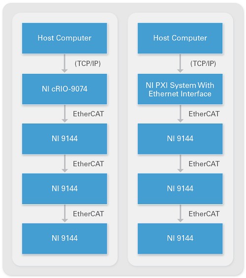
Figure 1. Typical EtherCAT System Using NI Master Controllers and Distributed Slave Devices
Why Add FPGA Intelligence?
You can program the EtherCAT RIO slave chassis with both the LabVIEW Real-Time and LabVIEW FPGA modules. Programming in the NI Scan Mode with LabVIEW Real-Time provides an expedient out-of-box experience for easy expansion I/O. NI Scan Mode gives you instant access to the physical I/O values on the EtherCAT RIO slave devices using simple drag-and-drop I/O variables, as well as live test panels to monitor system performance and do advanced troubleshooting. So, why add FPGA intelligence to your EtherCAT expansion I/O?
Programming the EtherCAT RIO slave chassis in FPGA Mode opens the doors to a new level of customization and flexibility for your application. By embedding decision-making capabilities, it reduces response time, quickly reacting to the environment without host interaction. The intelligent device can also offload processing from the master by conducting inline analysis, custom triggering, and signal manipulation at the node. Plus, using LabVIEW FPGA paves the way for domain experts to quickly prototype and implement their ideas without having to be a VHDL programmer.
Differences in the LabVIEW FPGA Programming API
If you are familiar with programming in LabVIEW FPGA for CompactRIO and other NI reconfigurable I/O platforms, there are some differences between programming the local FPGA and the FPGA for EtherCAT RIO. In LabVIEW 2009, NI introduced user-defined I/O variables to synchronize the slave's FPGA data with the master's real-time processing. These user-defined I/O variables are also the only means for transferring data between the controller’s real-time program and the expansion chassis’ FPGA program.
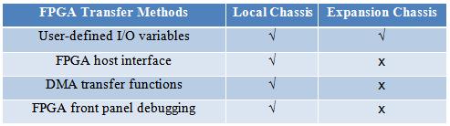
Table 1. Compare FPGA transfer methods for local versus expansion chassis.
After you add the FPGA target to the EtherCAT RIO slave in the LabVIEW project window, you can create a user-defined I/O variable by right-clicking on the EtherCAT RIO device and selecting Add»User-Defined Variable. You can set the variable name, data type, and data direction (from host to FPGA or vice versa) from the Properties window. It is important to note that there is a limit to the number of user-defined I/O variables that you can create in the slave's FPGA Mode. The EtherCAT RIO can hold a total of 512 bytes of input data and 512 bytes of output data for both I/O variables in Scan Mode and user-defined I/O variables in FPGA Mode. For example, if you are using four 32-channel modules in Scan Mode and each channel takes up 32 bits of data, then Scan Mode I/O variables are using 256 bytes of input data. With the remaining 256 bytes of input data, you can create up to 64 input user-defined I/O variables (also of 32-bit length) in FPGA Mode.
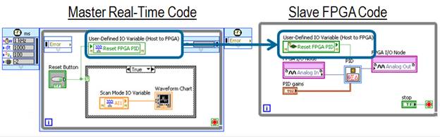
Figure 2. Create user-defined I/O variables to communicate between the master's real-time code and the slave's FPGA code.
Special FPGA Features and Use Cases
These user-defined I/O variables transfer single-point data to and from the master controller at each scan cycle, so they are best used for passing processed data from the EtherCAT RIO expansion chassis. For example, in an NIWeek 2009 keynote, presenters used six EtherCAT RIO slave chassis to ring several musical chimes that played a song. The master real-time code controlled the timing of when to ring each distributed chime, but the FPGA on the slave chassis recorded the audio waveform measurements from a microphone and performed a fast Fourier transform (FFT) to get the sound intensity for a specific chime frequency. The slave FPGA then used pulse width modulation (PWM) to control the brightness of a series of LEDs to match the loudness of the chimes. Even without the real-time program running, these LEDs would also react to other loud sounds at the same chime frequencies because of the FPGA logic on the EtherCAT RIO expansion chassis.
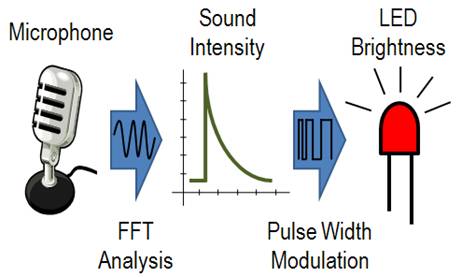
Figure 3. This EtherCAT RIO FPGA code was used in an NIWeek 2009 keynote demo to ring several musical chimes that played a song.
In addition to using the LabVIEW FPGA algorithm functions, the slave chassis provides several chassis I/O signals to help customize and synchronize your code. For example, with EtherCAT State you can execute certain FPGA logic during one of the seven EtherCAT states. Therefore, if communication with the master controller ceases, the EtherCAT RIO expansion chassis will enter the safe-operational state and the FPGA code can specify the appropriate safe state behavior. Another set of useful signals is the Output and Input Virtual Point. These two timing signals indicate exactly when each slave updates its output and input values during each scan period. Therefore their rising edges can be used to synchronize FPGA code on multiple EtherCAT RIO expansion chassis. LabVIEW examples are included in the NI-Industrial Communications for EtherCAT driver to demonstrate several advanced FPGA features, such as NI Scan Engine synchronization, specialty digital signals, and asynchronous oversampling.
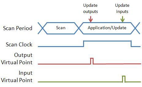
Figure 4. Synchronize your EtherCAT I/O FPGA code using virtual point timing signals.
Summary
Using deterministic distributed I/O such as the EtherCAT RIO expansion chassis ensures that you can maintain the tight timing and synchronization needed for real-time applications. Plus, adding hardware-level FPGA code to your EtherCAT RIO slaves gives you the ability to offload processing from the controller and reduce response time by making intelligent decisions at the node.