PCBA Functional Test Demo Test Sequence
- Aktualisiert2025-04-25
- 5 Minute(n) Lesezeit
PCBA Functional Test Demo Test Sequence
The PCBA FT Demo test sequence demonstrates testing PCBA DUTs in TestStand using the PCB Assembly Test Toolkit measurement libraries built in LabVIEW. Refer to the individual library documentation for more information about how to use each library in your own application.
Highlighted Features
The PCBA FT Demo sequence demonstrates the following features:- DAQ_Power Supply Source and Measure
- DAQ_DC-RMS Voltage Measurement
- DAQ_Static Digital State Generation
- DAQ_DC-RMS Voltage Measurement
- DAQ_DC Voltage Generation
- DAQ_Time Domain Measurement
- DAQ_Signal Voltage Generation
- DAQ_Frequency Domain Measurement
Setup Diagram
The following figures represent the simulated hardware setup used in this example sequence. Refer to individual device specifications for pinouts and relevant specifications.

The following table provides a detailed summary of the functional demo sequence test scenario.
| PCBA Functional Test Demo | LSL | USL | Units | Timing (s) | Test Points | V Mode | Analysis Value | Trigger | Procedure/Condition | Measurement Library |
|---|---|---|---|---|---|---|---|---|---|---|
| Power Diagnostics | ||||||||||
| To power up and measure start-up transition max pic current, idle power consumption, and DC regulators. | ||||||||||
| Start-up transition max pic current | 0 | 1 | A | 0.1 | TP_POWER0 | Ref | Max Current | Maintain existing value | Set Power On Voltage to 5 V, 3 A, Maintain Existing Value, Measure TP_Max Current (Pic Transition) | Power supply source and measure |
| Idle power consumption | 4.5 | 5.5 | W | 0.1 | TP_POWER0 | Ref | Idle Watt | Maintain existing value | Measure idle watt, Power voltage already On | Power supply source and measure |
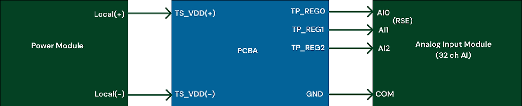
| DC Regulators | 0.9 | 1.1 | V | 0.1 | TP_REG0 | Ref | Average DC Voltage | No | Measure regulator voltage around 1 V | DC-RMS voltage measurement |
| - | 3.1 | 3.4 | V | - | TP_REG1 | Ref | Average DC Voltage | No | Measure regulator voltage around 3.3 V | - |
| - | 4.8 | 5.2 | V | - | TP_REG2 | Ref | Average DC Voltage | No | Measure regulator voltage around 5 V | - |
| Battery or charger voltage and current sleep mode | ||||||||||
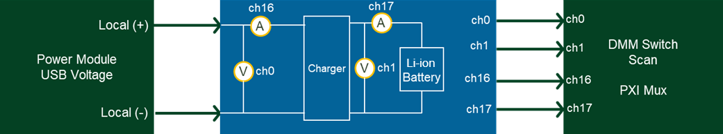
| USB Voltage | 4.75 | 5.25 | V | DMM 5.5 Dig | ch0 | Diff | DMM | No | Close all Current Shunts to Power the DUT, Scan ch0 | DMM Scan PXI MUX SHUNT Topology |
| Li-ion Battery Voltage | 2.5 | 4.25 | V | DMM 5.5 Dig | ch1 | Diff | DMM | No | Scan ch1, SOC dependent | - |
| USB Current | 0 | 500 | mA | DMM 5.5 Dig | ch16 | Diff | DMM | No | Scan ch16, SOC dependent | - |
| Li-ion Battery Current | 0 | 500 | mA | DMM 5.5 Dig | ch17 | Diff | DMM | No | Scan ch17, SOC dependent | - |
| Battery Voltage Sleep Mode | 2.5 | 4.25 | V | DMM 5.5 Dig | ch1 | Diff | DMM | No | Wait inactivity for 2 sec, Scan ch1 | New Scan |
| Battery Current Sleep Mode | 5 | 15 | µA | DMM 6.5 Dig | ch17 | Diff | DMM | No | Scan ch17 | - |
| Reset and self-test | ||||||||||
| To simulate Push Reset Button On/Off condition for 0.1 sec followed by a 5 sec wait for reboot to check voltage values on power and status LEDs. | ||||||||||
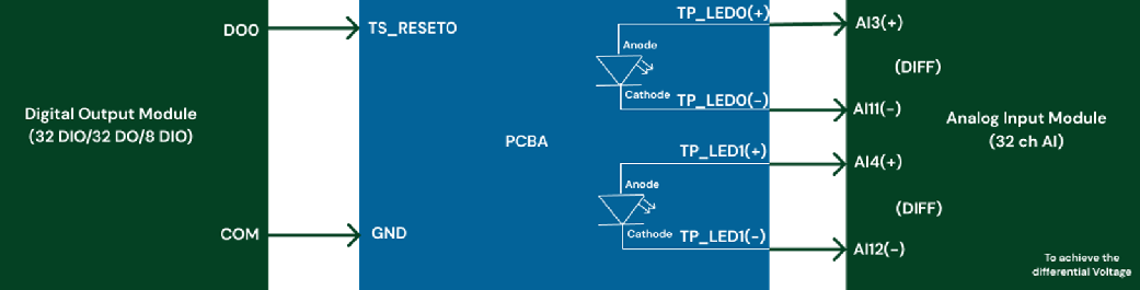
| Push button reset | V | Wait for 0.1 sec followed by a 5 sec wait for reboot | TP_RESET0 | Ref | Switch ON 0.1 sec then switch OFF with digital output (DO Module switch), Wait Reboot for 5 sec | Static digital state generation | ||||
| Power LED0 RED | 1.8 | 2.2 | V | 0.1 | TP_LED0 | Diff | Average DC Voltage | No | Measure value for state (LED Power) | DC-RMS voltage measurement |
| Status LED1 GREEN | 2.6 | 3.2 | V | - | TP_LED1 | Diff | Average DC Voltage | No | Measure value for state (LED Status) | - |
| Animation and sound user input test | ||||||||||
| To simulate the push on a volume button to generate a sound and a light animation to the LED. | ||||||||||
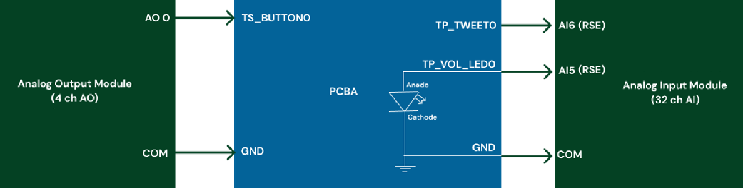
| Push action button | 0.5 | TS_Button0 | Ref | No | Generate DC 3.3 V to simulate Button On | DC voltage generation | ||||
| Animation action LED | 25% | 35% | Duty cycle | 0.5 | TP_VOL_LED0 | Ref | TDM Voltage Duty Cycle | Trigger on button | Measure PWM square signal On Volume LED | Time domain measurement |
| Tone action sound check | 990 | 1010 | Hz | 0.5 | TP_TWEET0 | Ref | TDM Voltage Frequency | - | Measure 1 kHz frequency on Tweeter | - |
| Audio filter test | ||||||||||
| To test if measured tones frequency are within ±10% of tolerance | ||||||||||
| Send multi-tone audio | 0.1 | TP_LineIn | Ref | Send 4 tones: 10 Hz, 100 Hz, 1 kHz, 10 kHz, 1 V sine signal | Signal voltage generation | |||||
| Measure tone | -10% | +10% | Hz | 0.1 | TP_LineOut | Ref | Detected Tones Frequencies (0, 1, 2, 3) | Trigger from signal generation | Measure 4 tones: 10 Hz, 100 Hz, 1 kHz, 10 kHz | Frequency domain measurement |
| - | -10% | +10% | V | 0.1 | - | Ref | Detected Tones Amplitudes (0, 1, 2, 3) | - | Measure 4 voltage amplitudes | - |