Signal-based Synchronization of Analog Input C Series Modules with NI-DAQmx in LabVIEW
Overview
CompactDAQ controllers and chassis offer support for a wide variety of C Series I/O modules with diverse measurement types such as acceleration, temperature, and strain. When applications require tight synchronization between measurements, the CompactDAQ hardware in conjunction with the NI-DAQmx API allow users flexible configuration options to achieve the desired level of synchronization across multiple C Series I/O modules. This document highlights signal-based options available to achieve synchronization between C Series I/O modules.
Contents
- C Series Analog Input Modules
- Time-Based Synchronization vs. Signal-Based Synchronization
- Start Trigger Synchronization
- Sample Clock Synchronization
- Multidevice Task
- Multirate Synchronization
- MultiChassis Tasks
- Conclusion
- Additional Resources
C Series Analog Input Modules
C Series Analog Input Modules can be categorized into four groups based on their synchronization: Reference Clocked, Delta Sigma, Slow Sampled, and Successive Approximation Register (SAR). Reference Clocked modules convert using an internal onboard clock. This onboard clock is disciplined using a phase lock loop to another internal clock or can be disciplined to clocks external to the module. Delta Sigma Modules use a 24-bit ADC and convert using a clock internal to the module. Slow Sampled Modules use a 24-bit ADC and convert using an external clock that originates from the CompactDAQ controller or chassis. Lastly, SAR Modules use a Successive Approximation ADC (12- or 16-bit) and convert using an external clock. The method of implementing synchronization may depend on the group that the module falls into. A list of module groupings can be found in the Resources section of this tutorial. In this tutorial, synchronization is defined as the steps or techniques used directly or indirectly via the DAQmx driver to start measurements at the same time and to remove drift between subsequent measurements. While the result of these steps increases the sample to sample alignment, the focus is to prevent drift.
Time-Based Synchronization vs. Signal-Based Synchronization
Time-based synchronization and signal-based synchronization are two distinct synchronization paradigms that you can use to synchronize measurements with C Series modules. This document discusses signal-based synchronization. For details regarding time-based synchronization, please view Time-based Synchronization of Analog Input C Series Modules with NI-DAQmx in LabVIEW.
- Signal-based synchronization describes synchronization via signals routed between devices. A device which waits on a digital high to occur on a trigger line is using signal-based synchronization.
- Time-based synchronization describes synchronization via events scheduled with respect to the time on a device. A device which waits on the local time to reach 5:00 PM to start is using time-based synchronization.
Each method of synchronization has its advantages and the right synchronization method varies by application.
Start Trigger Synchronization
This section outlines different methods to control when acquisition begins across multiple modules. Because the focus is to simply align the start time across multiple tasks, this method is the most rudimentary way to achieve synchronization.
The first method uses a software function that, when executed, starts acquisition as defined by one DAQmx task. When this function executes in each task at relatively the same time, a similar level of synchronization is seen in the start of the data.
When hardware timing is used and no triggers are configured, executing the DAQmx Start Task VI will initiate the acquisition. This VI causes the CompactDAQ Controller and Chassis to send a digital pulse that begins the acquisition. If the DAQmx Start Task VIs of two independent tasks are placed in the same frame of a flat sequence structure, then the two tasks begin at the same relative time. However, the separation between the exact start times of the two tasks depends on the software time delay between the executions of the DAQmx Start Task VIs and will therefore vary due to the Operating System. This method is seen in figure 1 where the start of two analog input tasks is controlled during runtime with the DAQmx Start Task VIs inside the same frame of a flat sequence structure.
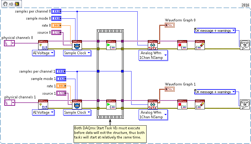
Figure 1: Start of Each Task Occurs Inside Flat Sequence Structure
To avoid the delay, the DAQmx Trigger VI can be used. This method can configure tasks to start upon a hardware trigger rather than by calling a software function. When using this feature to synchronize tasks, one task will be sending the trigger, and the other task will be receiving the trigger. The task receiving the trigger will wait for the trigger sent from the master task to begin acquisition or generation. When the master task starts, a digital trigger is sent from the master task and starts any task configured to start based upon this signal. This method is seen in the Figure 2 where the DAQmx Control Task VI is called before the task accepting the ai/Start Trigger ensuring that the Master Task reserves the ai/Start Trigger.
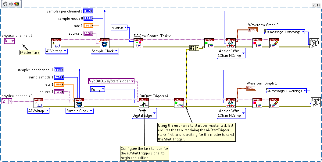
Figure 2: Trigger Configuration to Start Both Tasks
To understand trigger and timing nomenclature, you must know which timing engine is reserved for a task. CompactDAQ controllers and chassis have three analog input timing engines: ai, te0, and te1. Each concurrently run task is assigned to a different timing engine to control the sample clock and triggers. For example, the ai/StartTrigger is assigned to the ai timing engine. The NI-DAQmx driver automatically assigns each analog input task to a timing engine starting with ai, then te0, and finally te1. It is important to know which task is using which timing engine, so we set tasks receiving the start trigger to use the signal from the same master task’s timing engine. By reserving the master task first, we are assigning this task specifically to the ai timing engine. Now both tasks can be set to use the master task’s start trigger (ai/StartTrigger).
Sample Clock Synchronization
Using the above technique, tasks are started at the same time by sharing a start trigger. However, this method will not guarantee that the timing of subsequent measurements between the two tasks will not drift away from each other. A sample clock can be shared between both tasks, so that any task that uses the shared clock can take samples at the same time. Therefore, the two tasks will not drift from each other. As discussed earlier, Compact DAQ controllers and chassis have three analog input timing engines, so the order in which the tasks are reserved will determine the timing engines used by each task. Figure 3 below details how to share the sample clock between tasks.
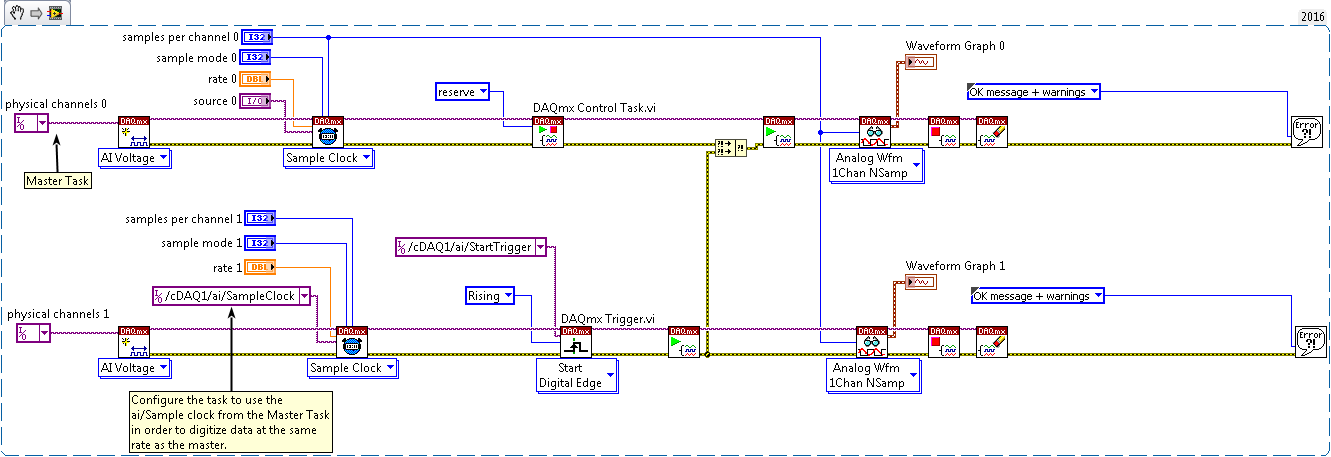
Figure 3: Sample Clock and Trigger is Shared
Since each task shares the same sample clock, this technique requires that the two tasks operate at the same sample rate. This method of synchronization will not work for Delta Sigma or Reference Clocked Modules. These modules use a clock onboard the module to acquire their measurements. The following sections (Multidevice Task and Multirate Tasks) will discuss how to synchronize Delta Sigma Modules.
Multidevice Task
To help simplify synchronization configuration, NI-DAQmx allows multiple Analog Input channels from various modules to be placed in the same task. To place various modules in the same task, specify multiple channels across different modules in the Physical Channel input to the Create Virtual Channel VI. Channels from different modules should be included in the same DAQmx Create Channel if they are intended to have the same measurement configuration (voltage range, and units) and the same timing and triggering information.

Figure 4: Using different modules in the same task
If the modules are taking different measurements (such as voltage or current), require different measurement ranges, or need to use different measurement units then use multiple instances of the DAQmx Create Virtual Channel VI as seen below.

Figure 5: Multiple DAQmx Create Virtual Channel VIs used for one task to specify different measurement types
You can mix different types of analog input modules (SAR, Delta Sigma, Slow Sampled, and Reference Clocked) in the same task and allow the NI-DAQmx Driver to synchronize them for you. With Multidevice Tasks, DAQmx chooses the best possible method to synchronize the modules. An explanation is provided below of different scenarios and how Multidevice Task synchronizes the measurements.
Two SAR/Slow Sampled Modules - When two SAR modules, SAR and Slow Sampled modules, or two Slow Sampled Modules are placed in the same hardware timed task, the DAQmx driver shares the same chassis or controller’s sample clock and start trigger between both modules. For the SAR and Slow Sampled Module configuration, the maximum rate that data is returned is not determined by the Slow Sampled Module. The driver will return duplicate samples for the Slow Sampled module to allow you to run the SAR module at the fastest allowable rate.
Two Delta Sigma Modules - When two Delta Sigma Modules are placed in the same hardware timed AI task, the DAQmx driver shares the fastest master timebase between all the modules, resets their ADCs based on the same synchronization pulse, shares a start trigger, and adjusts the reset time. The master timebase is the internal 12.8 MHz or 13.1 MHz clock that Delta Sigma Modules use to acquire measurements. The default behavior for an cDAQ-9185 or cDAQ-9189 (time-aware chassis) is that the master timebase originates from the chassis instead of the module with the fastest master timebase.
Two Reference Clocked Modules - When two Reference Clocked Modules are placed in the same hardware timed AI task, the DAQmx driver shares the reference clock from the master module to the other module, resets their ADCs based on the same synchronization pulse, shares a start trigger, and adjusts the reset time. The reference clock is the internal master timebase that the subsequent module locks onto. The default behavior for a time-aware chassis is that the reference clock originates from the chassis instead of the master module.
Reference Clocked Module and Delta Sigma Module - When a Reference Clocked Module and Delta Sigma Module are placed in the same hardware-timed AI task, the DAQmx driver routes the Reference Clocked Module’s reference clock to the Delta Sigma Module’s master timebase. Both modules receive a synchronization pulse from the chassis/controller that resets their respective ADCs and share a start trigger, and each module’s reset time is adjusted. In a time-aware chassis, the Reference Clocked Module’s reference clock is not shared with the Delta Sigma Module’s master timebase rather the chassis routes a reference clock to the Reference Clocked Module and a master timebase to the Delta Sigma Module. The Reference Clocked Module (NI 9775) cannot be in record mode when placed in the same task as a Delta Sigma Module.
Delta Sigma/Reference Clock and SAR/Slow Sampled - When a SAR or Slow Sampled Module and a Delta Sigma or Reference Clocked Module are placed in the same hardware timed AI task, the DAQmx driver configures the Delta Sigma Module or Reference Clocked Module to export its internal sample clock to be used by the SAR or Slow Sampled Module. The internal sample clock is equivalent to the data rate configured for the Delta Sigma Module
where
fs is the data rate
fm is the internal master timebase specified in each modules specification sheet
n/a/b are divisors.
The internal sample clock for the Reference Clocked Module can be found in the device’s Datasheet. The driver will return duplicate samples for the Slow Sampled Module, which allows the Delta Sigma or Reference Clocked Module to run at a faster rate. The Reference Clocked Module (NI 9775) cannot be in record mode when placed in the same task as a SAR or Slow Sampled module.
Multirate Synchronization
When referencing multiple modules in one task, the same sampling rate will apply to all channels. However, some applications may require synchronization at different rates.
Two SAR Modules - You do not need to do any additional work to synchronize two SAR Modules or Slow Sampled modules acquiring at different rates in a CompactDAQ chassis or controllers besides sharing a Start Trigger. The sample clock each module uses is derived from the same signal. Thus, the measurements will be synchronized if the modules are in the same chassis.
Two DSA Modules - To synchronize two Delta Sigma Modules acquiring at different rates, set the tasks to share a common master timebase, synchronization pulse (sync pulse), and start trigger. The master timebase clock is routed from one module to another in the Figure 6. Note that the NI DAQmx Timing Property node SampleClck.Timebase.Src refers to the same 12.8 MHz or 13.1 MHz signal as the master timebase listed in the Operating Instructions and Specifications/Datasheet. This clock is also known as an oversample clock because there are many ticks of this clock required to produce one sample.
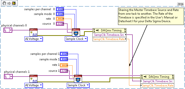
Figure 6: Sharing the over sample clock
A device that uses a Delta Sigma Module has a free-running ADC. Sharing the master timebase will ensure that measurements are derived from the same clock, but there will be an unknown phase shift due to the exact start of the ADC. The next step is sharing the synchronization pulse. The sync pulse is used to reset the ADC/DAC before it begins acquiring or generating samples. Without this signal to reset the ADC/DAC, measurements taken will not be synchronized. Below, the property nodes are shown that allow the sharing of an oversample clock and a sync pulse.

Figure 7: Sharing over sample clock, start trigger and sync pulse.
The above configuration routes the synchronization pulse from one task to another depending on which task is running at a faster rate. For multirate configuration, we use the sample clock of the slower running task to trigger the faster running task. The reasoning for this is explained in the example.
One more consideration to study is the reset time required by each module. The reset time is a delay required by a Delta Sigma Modules ADC after it has received the synchronization pulse until it begins acquiring data. Different model Delta Sigma Modules may have different reset times. You need to account for this reset time to ensure each device has gone through the reset sequence and begins to acquire or output samples at the same time. To properly account for potentially different reset times, the reset time required for each module is checked and, if necessary, a delay added to modules with a shorter reset time. Therefore, the sum of the reset time and the delay should be the same for each module.
The time needed to reset the ADC can be found using the DAQmx Timing Property Node SyncPulse.ResetTime. To ensure all ADCs end their reset cycle coincidentally, a comparison is made between both tasks’ reset time. We take the task with the largest Reset Time and subtract the Reset Time of the task with the smaller Reset Time. The result is the time where the one task has begun to acquire data while the other task is still going through its reset cycle. To account for this delay we use another NI-DAQmx property called SyncPulse.ResetDelay. This property allows a delay in the sync pulse that will be sent to each module. As previously stated the reset time is the delay between when the ADC receives a sync pulse and begins to acquire data. To best use this property, you should set this equal to the difference between the module that has the greatest reset time and the reset time of the module. This will shift the synchronization pulse of a module that takes less time to reset thus ensuring that both modules with a slow and fast reset time end their reset sequence at the same time. The code below details how to get the reset time and determine the appropriate reset delay.
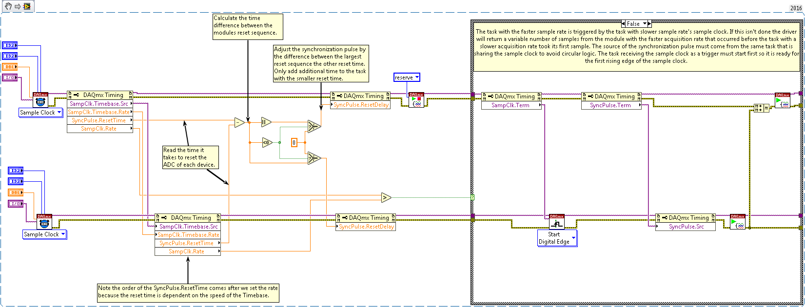
Figure 8: Sync Pulse reset time query and calculating the reset delay
The NI-DAQmx property node SyncPulse.ResetDelay has a maximum input of .013 seconds, which may not be suitable for large differences in the Reset Delay values of differing modules. Note the order of the property node when polling for the SyncPulse.ResetTime on the task receiving the master timebase. The value will change depending on a 13.1 MHz Timebase or 12.8 MHz Timebase. Thus, it is important to call the SyncPulse.ResetTime on this task after the module has been informed of the Master Timebase’s rate.
When searching for the properties SyncPulse.ResetDelay and SyncPulse.ResetTime, you will also encounter SyncPulse.SyncTime and SyncPulse.MinDelaytoStart. Most developers will not use this property but may encounter them due to their similarity in name and proximity in location. SyncPulse.SyncTime is the SynchPulseResetTime y plus the value you enter for SyncPulse.ResetDelay. The value of SyncPulse.SyncTime is rounded to the nearest millisecond. SyncPulse.MinDelaytoStart is the time between when the Synchronization Pulse is issued and master task issues the start trigger. This property is equal to SyncPulse.SynchTime unless explicitly set.
Two Reference Clocked Modules -To synchronize two Reference Clocked Modules at different rates (like two DSA Modules), distribute the master task’s reference clock, synchronization pulse, and sample clock to other tasks. Note that the NI DAQmx Timing Property node RefClck.Src refers to the same Internal master timebase listed in the Datasheet.
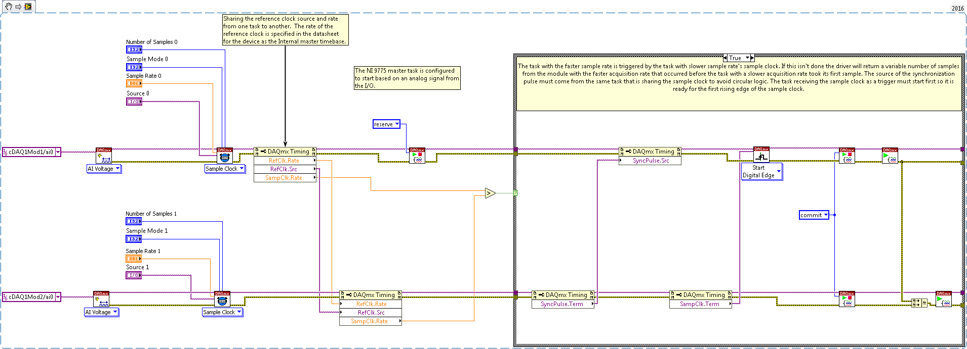
Figure 9: Synchronizing Two Reference Clocked Modules
Delta Sigma Module and SAR/Slow Sampled Module – To synchronize a Delta Sigma Module and SAR/Slow Sampled Module, share the Delta Sigma Module’s master timebase and sample clock with the SAR/Slow Sampled Module. Since the SAR/Slow Sampled Module cannot acquire at 12.8 MHz or 13.1 MHz the Delta Sigma’s master timebase is shared with the master timebase of the SAR/Slow Sampled Module as depicted in figure 10. The sample clock of a SAR/Slow Sampled Module is typically derived from the CompactDAQ Chassis or Controller’s onboard clock. This method replaces the chassis or controller clock with the 12.8 MHz or 13.1 MHz clock from the Delta Sigma Module.

Figure 10: Synchronizing a Delta Sigma Module and SAR/Slow Sampled Module
Reference Clocked Module and SAR/Slow Sampled Module – To synchronize a Reference Clocked Module and SAR/Slow Sampled Module, share the Reference Clocked Module’s reference clock and sample clock with the SAR/Slow Sampled Module. Since the SAR/Slow Sampled Module cannot acquire at 12.8 MHz, the Reference Clocked Module’s reference clock is shared with the master timebase of the SAR/Slow Sampled Module. The sample clock of a SAR/Slow Sampled Module is typically derived from the CompactDAQ Chassis or Controller’s onboard clock. This method replaces the chassis or controller clock routed to the SAR/Slow Sampled Module with the Internal Master Timebase from the Reference Clocked Module.
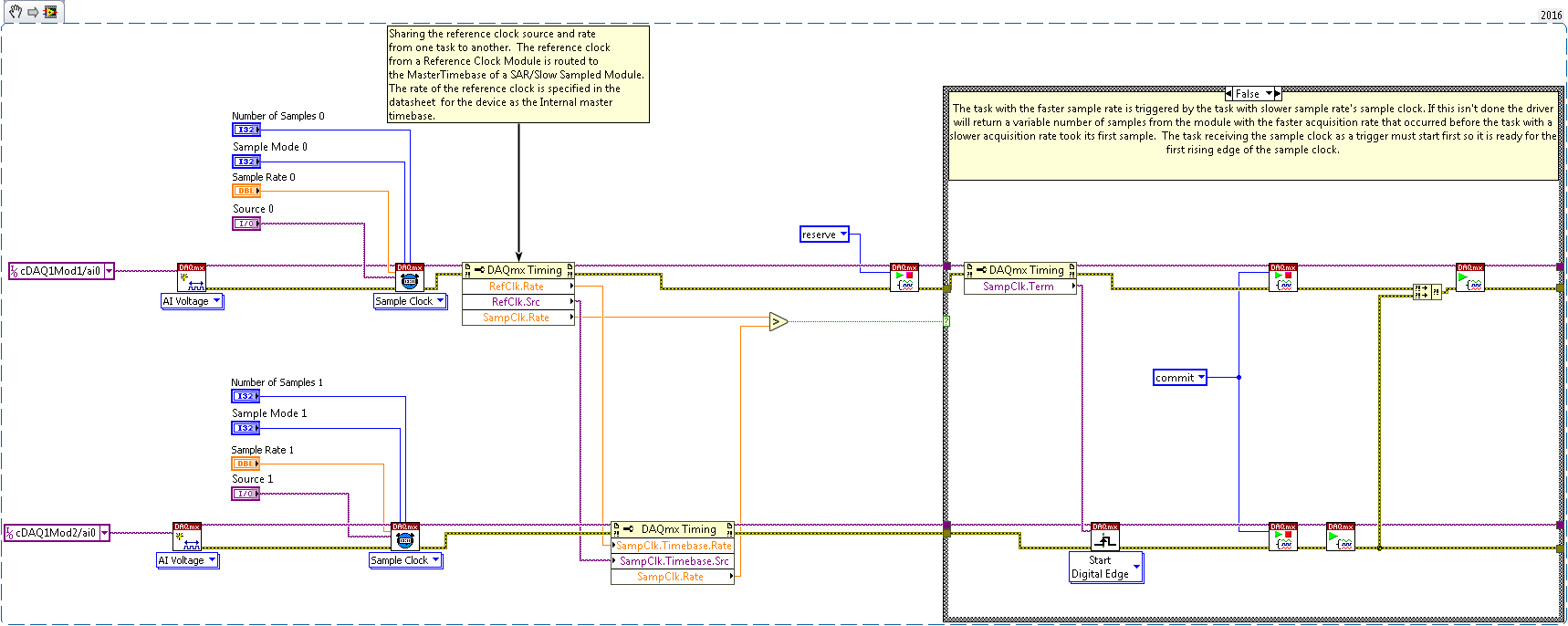
Figure 11: Synchronizing a Reference Clocked Module with a SAR/Slow Sampled Module
MultiChassis Tasks
Some measurement applications require mixed measurements and distributed systems, which might require more than one CompactDAQ chassis or controller. There are three main methods of multichassis synchronization.
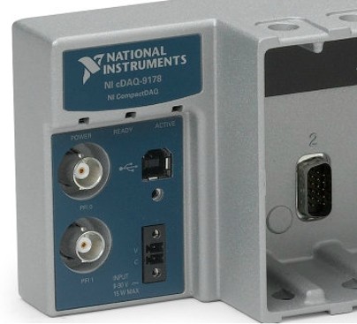
Multi Chassis Synchronization Using BNC/SMB Connectors or Digital Modules - One method to achieve synchronization between chassis is to use the two BNC connectors located on the cDAQ-9178, cDAQ-9188, cDAQ-9188XT, and cDAQ-9179 chassis or one SMB Connector on the CDAQ-9132, cDAQ-9133, cDAQ-9134, cDAQ-9135, cDAQ-9136, cDAQ-9137, cDAQ-9185, and cDAQ-9189 to import and export timing signals. Note that the CompactDAQ Controllers have now gone end of life and are no longer available.
Figure 12: NI cDAQ-9178 with two BNC ports can be used to import or export timing and trigger signals.
The BNC or SMB terminals of different chassis can be connected to route triggers and timing signals. Using the DAQmx driver, signals can be exported from a master task by using the NI-DAQmx Export Signal Property Node. On tasks (in another chassis), the Sample Clock and Start Trigger are configured to use the BNC or SMB terminals to accept signals.
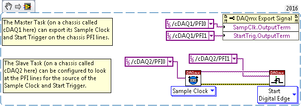
Figure 13: Configuring the BNC Ports on a CompactDAQ Chassis
Parallel/Correlated Digital IO Modules could also be used to receive or send trigger and timing signals across the chassis. These Digital I/O modules are preferred when there isn’t sufficient BNC or SMB ports on the NI Compact DAQ Controllers and Chassis or the signal bandwidths exceeds that of the BNC or SMB connector (1MHz).
Multichassis Synchronization Using the NI 9469 - The above method to configure timing and trigger signals across the chassis BNC connectors or a Parallel/Correlated Digital IO Modules may work for many applications. However, an alternative method using the NI 9469 is preferable in the following circumstances:
- Long distance between chassis
- High bandwidth of the exported signals
- Complex topology of synchronization
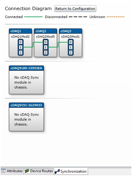
The NI 9469 allows simplified signal routing and coding and can offer synchronization to SAR, Slow-Sampled, Delta Sigma, Digital Input and Output, Analog Output modules in differing chassis topologies. The connections between the NI 9469 cards can be configured in Measurement & Automation Explorer (MAX) as shown in the following figure. Please see the related link section at the end of this document for more details on how to configure the NI 9469.
Figure 14: Configuration of NI 9469 in Measurement & Automation Explorer
Once the NI 9469 is configured in MAX (using NI-DAQmx version 9.9 or newer) any module in separate chassis can be added to the same task to greatly simplify the code required for synchronization. The following figure shows how this method of multichassis synchronization.

Figure 15: Multichassis Synchronization Code with NI 9469 Configured in MAX
The background process for how the modules are synchronized in different chassis is like the stated methods in the Multirate Tasks and Multidevice Tasks Sections. The limitation for which modules in multiple chassis can be synchronized automatically using this approach exists and is documented.
Conclusion
This tutorial has demonstrated several synchronization options. Initially, tasks were started with software-timed commands. You can improve the synchronization by sharing a hardware trigger between tasks and prevent drift between tasks by sharing a sample clock from one task to another. When synchronizing modules at the same rate, you can simplify the your programming by referring to several modules within the same task. If the modules you use require different sample rates, you must make special considerations depending on the type of module you are using. If the modules use require different rates, you must make special considerations depending on the type of module you are using. The options outlined above represent several different ways to synchronize C Series modules based on signals within the timing requirements of many applications.
Additional Resources
C Series Modules:
- Delta Sigma Modules: 9202, 9218, 9225, 9227, 9229, 9230, 9232, 9234, 9235, 9236, 9237, 9238, 9239, 9242, 9244, 9246, 9247, 9250, 9251
- Slow Sampled Modules: 9207, 9208, 9209, 9210, 9211, 9212, 9213, 9214, 9216, 9217, 9219, 9224, 9226, 9228
- SAR Modules: 9201, 9203, 9205, 9206, 9215, 9220, 9221, 9222, 9223
- Reference Clocked Module: 9775
- Chassis Synchronization Module: 9469
- Configuring the NI 9469 in Measurement & Automation Explorer
- Learn 10 Functions in NI-DAQmx and Handle 80 Percent of Your Data Acquisition Applications
- NI CompactDAQ Advisor
- Time-based Synchronization of Analog Input C Series Modules with NI-DAQmx in LabVIEW

