Differences Between Accuracy, Code Width and Bits of Resolution
Overview
Contents
Code Width Calculation
If you have a data acquisition (DAQ) card that has an Analog to Digital Converter (ADC) with specified bits of resolution, you can calculate the code width of the card using the formula:
Code Width = Range/(2^bits)
This calculation will determine the smallest change the ADC should be able to measure. You might expect to obtain an analog input measurement that falls within the calculated code width tolerance; however, when you take an actual measurement with the card, the reading falls outside of the calculated code width.
Why does this happen? The code width is a misleading source of determining the instrument's resolution. A better source of determining the instrument's resolution is the input noise specification.
Other Factors
There are also other variables besides resolution and input noise that affect the absolute accuracy of a Data Acquisition (DAQ) card.
Code width is a measure of how precisely the Analog to Digital Converter (ADC) can translate an analog signal into its digital form before it can be passed on to the computer.
However, before the signal can be received by the ADC, the following options must be specified:
- The proper input channel must be selected
- The appropriate amount of gain must be applied
- Some signal conditioning may need to occur
To see how these components come together, a hardware model taken from the M series DAQ user manual is shown below as an example:
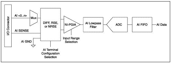
All of these components, including the ADC, will be affected by real world phenomena, which will introduce gain error, offset error, system noise, and temperature drift on the signal. Therefore, the resulting absolute accuracy of the device will depend on the environment that the card is used in.
The equation to calculate the expected noise is as follows:
Absolute Accuracy = ±((Input Voltage * % of reading) + Offset + System Noise + Temperature Drift
This formula requires a number of inputs that can all be referenced in tables that are typically found in the data and specifications sheets for the acquisition products. Some data sheets already have the absolute accuracy in various operating environments calculated for you. Click here to learn more about calculating absolute accuracy for your device, module or system.