RFmxCDMA2k SEM Fetch Upper Offset Power (Array) VI
- Updated2025-10-13
- 3 minute(s) read
Returns the arrays of upper offset segment power measurements.
Inputs/Outputs
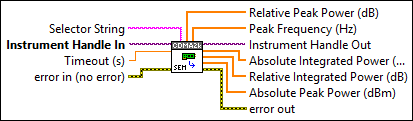
 Selector String
—
Selector String
—
Selector String specifies a selector string comprising of the signal name and result name. If you do not specify the signal name, the default signal instance is used. If you do not specify the result name, the default result instance is used. The default value is "" (empty string). Examples: "" "signal::sig1" "result::r1" "signal::sig1/result::r1" You can use the RFmxCDMA2k Build Signal String VI to build the selector string.  Instrument Handle In
—
Instrument Handle In
—
Instrument Handle In specifies the RFmx session refnum. Instrument Handle In is obtained from the RFmxInstr Initialize NIRFSA VI.  Timeout (s)
—
Timeout (s)
—
Timeout specifies the timeout for fetching the specified measurement. This value is expressed in seconds. Set this value to an appropriate time, longer than expected for fetching the measurement. A value of -1 specifies that the VI waits until the measurement is complete. The default value is 10.  error in (no error)
—
error in (no error)
—
error in describes error conditions that occur before this node runs. This input provides standard error in functionality.  Relative Peak Power (dB)
—
Relative Peak Power (dB)
—
Relative Peak Power returns the array of peak powers measured in each upper (positive) offset segment relative to the carrier absolute integrated power.
Peak Frequency (Hz)
—
Peak Frequency returns the array of frequencies at which the peak power occurred in each offset segment. This value is expressed in Hz.  Instrument Handle Out
—
Instrument Handle Out
—
Instrument Handle Out passes a reference to your RFmx session to the next VI.
Absolute Integrated Power (dBm)
—
Absolute Integrated Power returns the array of upper (positive) offset segment powers measured.
Relative Integrated Power (dB)
—
Relative Integrated Power returns the array of powers measured in each upper (positive) offset segment relative to the carrier absolute integrated power.
Absolute Peak Power (dBm)
—
Absolute Peak Power returns the array of peak powers measured in each upper (positive) offset segment. The power is measured in dBm.  error out
—
error out
—
error out contains error information. This output provides standard error out functionality. |