Introduction to Frequency Modulation
- Updated2025-10-08
- 7 minute(s) read
Frequency modulation involves varying the Frequency of a carrier in order to transmit a signal. Frequency can be thought of as the rate of change of phase. In an un-modulated carrier, the phase would change at a constant rate. The unmodulated signal could be represented mathematically as illustrated below:

RFmx Waveform Creator supports generation of an FM Mono, FM Stereo, and FM RDS signal. To reduce distortion pre-emphasis can be applied to audio components of any of the FM signals generated.
Mono Signal
The generation of Mono signal involves Frequency modulating an audio signal to produce a FM signal.
Stereo Signal
In Stereo mode, both the left and right channels are encoded to form a Stereo signal. The first stage of stereo encoding is to from a Mono and Stereo components from the left and right channel. This is done as follows:
- Mono = left +right
- Stereo = left -right
The Stereo encoded signal consists of the flowing subcarriers:
- The Mono component
- A 19 kHz pilot tone
- A 38 kHz tone amplitude modulated by the Stereo component.
The subcarriers are summed together to form a composite stereo signal. The following figure shows a block diagram for the stereo coder.
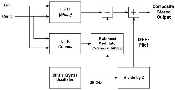
Fig. 7-1 Block Diagram for the stereo coder.
The following figure shows the baseband spectrum of the composite stereo output. The composite stereo output is fed to the FM modulator to produce a FM stereo signal.

Fig. 7-2 The baseband spectrum of the composite stereo output
RDS Signal
In the Radio Data System (RDS) mode, the left and right audio signal are encoded in the same way as in FM stereo. In Addition to the audio signal an Additional subcarrier is added to the signal.
The RDS sub carrier consists of an amplitude modulated 57 kHz tone.
The RDS subcarrier is combined with the stereo subcarriers and frequency modulated to form a FM RDS signal.
The RDS data is transmitted at 1187.5 bps. Before the data is used to amplitude modulate the sub carrier the following processes are carried out.
- Differential Encoding
- Bi-Phase Encoding
- Up sampling and Filtering (Pulse Shaping)
Differential Encoding
The RDS data is differentially encoded according to the rules mentioned in the following table.

Table 7-1 Differential encoding rules
Bi-Phase Encoding
Bi-Phase coding involves transmitting two impulses per bit. The first impulse is transmitted at time t, and the second impulse is transmitted at time t+td/2 where td = 1/1187.5*S. If the bit transmitted at time t is a 1 then a positive impulse is transmitted at time t, and a negative impulse is transmitted at time t+td/2. If a zero is transmitted at time t then a negative impulse is transmitted at time t, and a positive impulse is transmitted at time t+td/2. The Bi-Phase Encoding results in 2375 impulses being transmitted every second.
Up sampling and Filtering (Pulse Shaping)
After Bi-Phase coding the sample rate for the RDS data is 2375 Hz. Before the data is used to amplitude modulate the 57 kHz carrier the data is up sampled and filtered. The up sampling is done by inserting zeros between impulses. After the data has been up sampled a pulse shaping filter is applied. The following figures show the frequency response of the filter used for the RDS data.

Fig. 7-3 Equation of the frequency response of the filter used for the RDS Data

Fig. 7-4 The frequency response of the filter used for the RDS Data
RDS Data Structure
The RDS data is transmitted in groups of 104 bits. Each group is divided into 4 blocks of 26 bits. Each block consists of 16 information bits and 10 check word bits. The following figure shows the structure of the RDS Group.
Fig. 7-5 The structure of an RDS Group
To compute the checkword, a CRC (Cyclic redundancy check) is computed. The CRC is remainder of the following modulo 2 calculation m(x)*x10 where g(x) is the generator polynomial g(x)=x10+ x8+ x7+ x5+ x4+ x3+1.
The checkword is computed by taking a modulo 2 sum of the CRC and an “offset word”. The offset word is different for each group in the block, the offset words A, B, C, or C' and D are added to the CRC computed for blocks 1, 2, 3, and 4 respectively. Where offset words A, B, C, C' and D are defined in the following table.

Table 7-2 Definition of the offset words used to compute the check word
The bits in an RDS group are transmitted MSB first. The first block of every group always contains the PI code (program identification code). In the second group; the first 4 bits contain the Group type code; the 5th bit contains the version code; the 6th bit is the TP bit (Traffic program code); and bits 7 to 11 contain the PTY (Program type code). The remaining bits of group 2 and the bits in all the other groups are dependent on the group type and version bit. The following figure shows the basic RDS message format.
Fig. 7-6 The basic RDS message format
When a version A group is transmitted (B0=0 ) the PI code will only be transmitted in block 1, and the checkword of block 3 will be formed using offset word c. When a version B group is transmitted (B0=1) the PI is transmitted in both Block 1 and Block 3. In this situation the checkword of block 3 will be formed using offset word c'. By using a different offset word for a version B group it is possible for a receiver to detect that block 3 contains the PI code without reading the version bit transmitted in block 1.
PI (Program identification) Code
The Program identification code is used to identify the program being transmitted. The use of the PI code varies from country to country, but in most countries it takes the following format:
Bits b15 to b12= Country code.
Bits b11 to b8= Program type in terms of area coverage.
Bits b7 to b0 = Program reference number.
Group Type Code / Version
The Group type code and version indicate the type of message that is transmitted in an RDS signal the group type is 4 bits long and the version code is 1 bit long. This provides 32 possible combinations of group/version codes. The following table shows the group types used in RDS mode. Currently RFmx Waveform Creator is only able to encode the messages in bold.

Table 7-3 group types used in RDS
The details of specific message types can be found in the RDS specification (IEC 62106).
TP (Traffic Program) Code
The TP code is used to indicate that a program carries traffic announcements. The TP code is a single bit. A value of 1 indicates that program carries traffic announcements, and a value of zero indicates the program does not. The TP code is used in conjunction with the TA(Traffic Announcement) code. The TA code is transmitted in a Tuning and switching message or a Fast switching message.
EON (Enhanced Other Network) messages may be used to provide information about other programs that carry traffic announcements. When the TP code is set to 0 the TA code is used to indicate whether or not the program carries EON information for Traffic Announcements.
When the TP code is set to 1 the TA code is used to indicate weather a Traffic Announcement is currently being broadcast. In this situation the TA code no longer indicates the presence/absence of EON information for Traffic announcements. The following table shows how the TP and TA codes are interpreted.

Table 7-4 How the TP and TA codes are interpreted.
PTY (Program Type) Code
The PTY code indicates the type of program that is being transmitted the program type is a 5 bit value and can take one of the following values:
- None = 0
- News = 1
- Current Affairs = 2
- Information = 3
- Sport = 4
- Education = 5
- Drama = 6
- Culture = 7
- Science = 8
- Varied = 9
- Pop Music = 10
- Rock Music = 11
- Easy Music = 12
- Light Classical = 13
- Seriously Classical = 14
- Other Music = 15
- Weather = 16
- Finance = 17
- Children = 18
- Social Affairs = 19
- Religion = 20
- Phone In = 21
- Travel = 22
- Leisure = 23
- Jazz Music = 24
- Country Music = 25
- National Music = 26
- Oldies Music = 27
- Folk Music = 28
- Documentary = 29
- Alarm Test = 30
- Alarm = 31