3D Cartesian Coordinate Rotation (Euler) (Scalar) VI
- Updated2025-07-30
- 4 minute(s) read
Rotates a three-dimensional Cartesian coordinate system in the counterclockwise direction using the Euler angles method and returns the new coordinate of the given point. Wire data to the X input to determine the polymorphic instance to use or manually select the instance.

Inputs/Outputs
 x
—
x
—
x is the real input x-component for the two-element vector.
y
—
y is the real input y-component for the two-element vector.
z
—
z specifies the input z-coordinate.  Euler Angles
—
Euler Angles
—
Euler Angles specifies the Euler angles in radians.
 rotation order
—
rotation order
—
rotation order specifies the order of the axes to rotate the coordinates around. For example, X-Y-Z specifies the first, second, and third rotations are about the x-, y-, and z-axes respectively. Z-X-Z is the default order.
 x out
—
x out
—
x out returns the rotated x-coordinate.
y out
—
y out returns the rotated y-coordinate.
z out
—
z out returns the rotated z-coordinate.  error
—
error
—
error returns any error or warning from the VI. You can wire error to the Error Cluster From Error Code VI to convert the error code or warning into an error cluster. |
According to Euler's rotation theory, you can describe a coordinate rotation with the Euler angles ϕ, θ, and ψ as shown below (use the default rotation order Z-X-Z as an example):
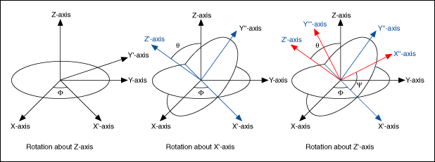
The following three steps describe the rotation:
- Rotate the X-, Y-, and Z-axes about the Z-axis by ϕ (–π < ϕ ≤ π), resulting in the X'-, Y'-, and Z-axes.
- Rotate the X'-, Y'-, and Z-axes about the X'-axis by θ (0 ≤ θ ≤ π), resulting in the X'-, Y''-, and Z'-axes.
- Rotate the X'-, Y''-, and Z'-axes about the Z'-axis by ψ (–π < ψ ≤ π), resulting in the X''-, Y'''-, and Z'-axes.
If you express the rotation of point (x, y, z) in terms of the following three matrices B, C, and D:
 ;
;  ;
;  ,
,
the coordinates, (x', y', z'), of the point in the new coordinate frame are

where A = BCD.