Wiring to the TRC-8543
- Updated2026-08-20
- 4 minute(s) read
Wiring to the TRC-8543
The TRC-8543 is used with an NI-XNET interface host port.

The TRC-8543 has one 9-pin male D-Sub connector that provides connections to a CAN bus. The TRC-8543 has pins for CAN_H and CAN_L, to which you connect the CAN bus signals. Connect these signals using twisted-pair cable.
The port has two common pins (COM) that are internally connected to the TRC-8543 isolated reference and serve as the reference ground for CAN_H and CAN_L. You can connect the CAN bus reference ground (sometimes referred to as CAN_V-) to one or both COM pins.
The D-Sub connector shell connects through the TRC-8543 shielding to the connector on the host port end. The shielding does not electrically connect to the COM signals.
The TRC-8543 receives power from the NI-XNET host port, but also requires an external power supply of +9 V to +30 V to operate in Low-Speed/Fault-Tolerant mode. Supply power from the CAN bus to the VSUP pin.
The TRC-8543 features software-selectable bus termination for both CAN High-Speed/Flexible Data-Rate and Low-Speed/Fault-Tolerant transceivers. For High-Speed/Flexible Data-Rate mode, you can enable 115 Ω of termination resistance between CAN_H and CAN_L through an API call. For Low-Speed/Fault-Tolerant mode, you can select either 1.11 kΩ or 4.99 kΩ of termination resistance for RTH and RTL through an API call (refer to the Termination Resistors section for more information). If you choose to use external termination, Table 4 lists recommended termination resistor values.
The following table lists the TRC-8543 pinout.
| Connector | Pin | Signal Name |
|---|---|---|

|
1 | No Connection (NC) |
| 2 | CAN_L | |
| 3 | COM | |
| 4 | NC | |
| 5 | NC | |
| 6 | COM | |
| 7 | CAN_H | |
| 8 | NC | |
| 9 | VSUP |
CAN Bus Topology and Termination
A CAN bus consists of two or more CAN nodes cabled together. The CAN_H and CAN_L pins of each node are connected to the main CAN bus cable through a short connection known as a “stub.” The pair of signal wires, CAN_H and CAN_L, constitutes a transmission line. If the transmission line is not terminated, each signal change on the bus causes reflections that may cause communication errors.
High-Speed/Flexible Data-Rate CAN
Because the CAN bus is bidirectional, both ends of the cable must be terminated. However, this requirement does not mean that every node on the bus should have a termination resistor; only the two nodes at the far end of the cable should have termination resistors.
The following figure shows a simplified diagram of a CAN bus with multiple CAN nodes and proper termination resistor (Rt) locations.

Low-Speed/Fault-Tolerant CAN
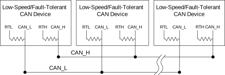
Every device on a low-speed/fault-tolerant CAN network requires a termination resistor for each CAN data line: RRTH for CAN_H and RRTL for CAN_L.
The following figure shows a simplified diagram of a low-speed/fault-tolerant CAN bus with termination resistor placements.
Connecting a High-Speed/Flexible Data-Rate CAN Bus
You can connect the TRC-8543 port to any location on a CAN bus.
The following figure shows one example of connecting the TRC-8543 directly to one CAN node.

Connecting a Low-Speed/Fault-Tolerant CAN Bus
You can connect the TRC-8543 to any location on a Low-Speed/Fault-Tolerant CAN bus.
The following figure shows one example of connecting the TRC-8543 directly to one CAN node.
