Connecting Digital Output Signals to a DAQ Device
Included in the Section
- Locating Your DAQ Device Pinout
- Configuring a Digital Output
- Wiring a Digital Signal to Your Device
- Testing the Signal
- Configuring Programmable Power-Up States
This document provides step-by-step instructions for wiring and configuring your NI DAQ device for digital output signals. Before you begin using your NI DAQ hardware, you must install your application development environment and NI-DAQmx driver software. Refer to the Installing LabVIEW and NI-DAQmx document for more information.
Digital Output Fundamentals
All digital signals have two discrete levels – a high level and a low level. Digital output devices control the state of the digital signals and can transition from one digital pulse to another. Digital output lines can be programmed on a line-by-line basis or programmed collectively as a port (typically four or eight lines). A counter device can also generate digital output pulses or pulse trains.
The four major types of digital output signals correspond to different digital logic families: TTL, sinking, sourcing, and relays. Your signal connections vary based on your load and your DAQ device.
TTL Digital Outputs
A transistor-transistor logic (TTL) compatible signal has the following characteristics:
- 0 V to 0.8 V = logic low
- 2 V to 5 V = logic high
Many NI DAQ devices feature TTL digital I/O lines. The number of digital lines varies from device to device, but all are bidirectional and all support the same logic levels. You can configure a line or a port as an input or an output in software. Most devices also feature pull-up or pull-down (or both) resistors on digital I/O lines to control the state of the lines when no signals are connected. Digital input applications include receiving TTL signals and sensing external device states, such as the state of the switch shown in the figure. Digital output applications include sending TTL signals and driving external devices, such as the LED shown in the figure.
Figure 1. TTL Digital I/O Connections
Sinking Digital Outputs
A sinking digital output means that the digital output (DO) terminal of a channel is driven to COM (ground reference) when the channel is turned on. A sinking output cannot provide power to an external device. Common terms for referring to a sinking device include NPN, Open Collector, Normally High, and IEC Negative Logic.
You can directly connect a sinking digital output channel to a variety of industrial devices such as solenoids, motors, actuators, relays, and lamps. Make sure the devices you connect to the digital output channel are compatible with the output specifications of the DAQ device. Refer to your device specification for more information.
Connect the external device to the DO terminal and the positive lead of the external power supply, and connect the negative lead of the power supply to the four COM terminals, as shown in Figure 2.

Figure 2. Connecting a Sourcing-Input Device to a Sinking Digital Output
If the module is switching an inductive or energy-storing device such as a solenoid, motor, or relay, and the device does not have flyback protection, install an external flyback diode as shown in Figure 3.

Figure 3. Connecting a Flyback Diode
Sourcing Digital Outputs
A sourcing digital output means that the digital output (DO) terminal is driven to Vsup when the channel is turned on. A sourcing digital output therefore provides power to an external device. Common terms for referring to a sourcing device include PNP, Open Emitter, Normally Low, and IEC Positive Logic.
You can directly connect a sourcing digital output channel to a variety of industrial devices such as solenoids, motors, actuators, relays, and lamps. Make sure the devices you connect to the output channel are compatible with the output specifications of the DAQ device. Refer to your device specifications for more information.
You must connect an external power supply to the sourcing digital output DAQ device. This power supply provides the current for the devices you connect to the digital output channels. Connect the positive lead of the power supply to Vsup and the negative lead of the power supply to COM. The Vsup pins on a digital I/O device are typically internally connected. In this case you can connect only one external voltage supply to the device. Refer to your device specifications section for information. Connect the external device or load to the DO terminal and connect the common of the device to COM (ground reference), as shown in Figure 4.

Figure 4. Connecting a Sinking-Input Device to a Sourcing-Digital Output
Relay Outputs
A relay channel has two interchangeable terminals, CHa and CHb. When connecting a load to the NI 9481 C Series sourcing digital output module, connect the positive lead of the load to either the CHa or the CHb terminal, and the ground of the load to one of the leads of the power supply. Connect the remaining CHa or CHb terminal to the other lead of the power supply. Figure 5 shows a possible configuration.

Figure 5. Connecting a Load to a Relay Output
When the channel is turned on, the terminal connected to the load drives current or applies voltage to the load. When the channel is off, the terminal does not drive current or apply voltage to the load.
When inductive loads are connected to relay outputs, a large counter-electromotive force may occur at switching time because of the energy stored in the inductive load. These flyback voltages can damage the relay outputs and/or the external power supply. Figure 6 shows examples of using an external flyback diode to protect DC inductive loads and an MOV to protect AC inductive loads.

Figure 6. Contact Protection for DC and AC Inductive Loads
Programmable Power-Up States
NI-DAQmx supports programmable power-up states for PFI and DIO lines on many NI DAQ devices. You can set the state of physical channels for some devices when your computer is powered on or the device is reset in NI-DAQmx. Software can program any value at power up to the PFI and DIO lines:
- A high-impedance input
- An output driving a 0
- An output driving a 1
Devices have limited numbers of writes to the EEPROM, so change power-up states infrequently.
Before connecting any signals, locate your device pinout.
- Open Measurement & Automation Explorer (MAX) and expand Devices and Interfaces.
- Right-click on your device name, and select “Device Pinouts.”
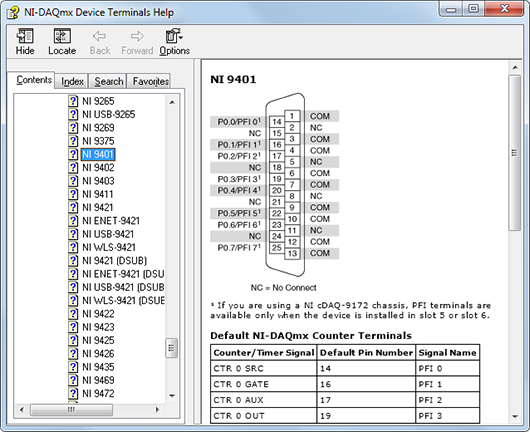
Figure 7. Device Terminals Help
The following terminal types correspond with digital output measurements:
- DO x: Digital Output — This is usually followed by a number corresponding to a channel number. For instance, if your DAQ device has eight digital output channels, your pinout diagram shows terminals for DO 0 through DO 7 throughout the connector.
- PFI: Programmable Function Input — This terminal can be configured through software to be a digital input or digital output channel.
- Px.y: Port X Line Y — This is the same as a digital output terminal (DO) specified as a line in a port for convenience.
- D GND: Digital Ground — This terminal is the ground reference for DO channels. On some multifunction DAQ devices D GND may be electrically connected with AI GND and AO GND.
- COM: Common — Common ground terminal for all DO channels. This ground may be isolated from earth ground, depending on your device.
You can use MAX to quickly verify the accuracy of your measurement system setup. Using an NI-DAQmx Global Virtual Channel you can configure a digital output generation without any programming. A virtual channel is a concept of the NI-DAQmx driver architecture used to represent a collection of device property settings that can include a name, a physical channel, input terminal connections, the type of measurement or generation, and scaling information.
Follow these steps to begin:
- With NI MAX open, select Data Neighborhood and click Create New.
- Select NI-DAQmx Global Virtual Channel and click Next.
- Select Generate Signals » Digital Output » Line Output

Figure 8. Creating an NI-DAQmx Virtual Channel
- Select line0 or whichever physical channel you intend to use to connect your digital output. A physical channel is a terminal or pin at which you can measure or generate an analog or digital signal.

Figure 9. Device Physical Channels
- Click Next and enter a name for the global virtual channel or leave the default.
- Click Finish to see the following screen in MAX:

Figure 10. Setting Up an Digital Output Channel in MAX
- On the Settings tab, click Invert Line if you want to reverse the polarity of the line.
The next step is to physically connect the digital signal to your digital output device. Your digital signal should match your output configuration. Connect a TTL signal to a bidirectional TTL output terminal (Figure 1). Connect a sourcing digital input device to a sinking digital output terminal (Figure 2). Connect a sinking digital input device to a sourcing digital output terminal (Figure 4). Connect the positive and negative leads of a load to CHa and CHb (or vice versa) of a relay output (Figure 5).
Use NI-DAQmx global virtual channels to preview your measurements.
- With MAX still open, click back on the NI-DAQmx Global Channel tab and click on the Run button.
- Click the radio button to toggle the digital output on and off.

Figure 11. Previewing a Digital Output Generation in MAX
You also have the option of saving your NI-DAQmx Global Virtual Channel should you wish to refer to this configuration screen again in the future.
If your device supports programmable power-up states (refer to your device specifications), follows these steps to configure your digital I/O lines in MAX.
- Right-click your device name under Devices and Interfaces and select Properties.
- Click the Power-up States tab. The digital lines of your device are organized by port (a group of lines).

Figure 12. Setting Power-Up States in MAX
- You can set the digital power-up state for each line to logic low, logic high, or tristate (floating). Use the Set All radio buttons to configure all lines in a port.