An Overview of the PXI Platform
Overview
Powered by software, PXI is a rugged PC-based platform for measurement and automation systems. PXI combines PCI electrical-bus features with the modular, Eurocard packaging of CompactPCI and then adds specialized synchronization buses and key software features. PXI is both a high-performance and low-cost deployment platform for applications such as manufacturing test, military and aerospace, machine monitoring, automotive, and industrial test. Developed in 1997 and launched in 1998, PXI is an open industry standard governed by the PXI Systems Alliance (PXISA), a group of more than 70 companies chartered to promote the PXI standard, ensure interoperability, and maintain the PXI specification across its mechanical, electrical, and software architectures.
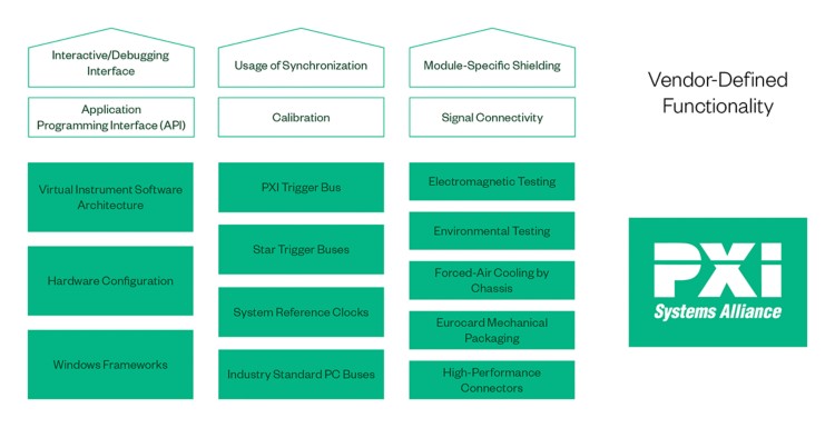
Figure 1: The PXISA defines requirements to ensure interoperability between vendors, and leaves flexibility for vendor-defined functionality.
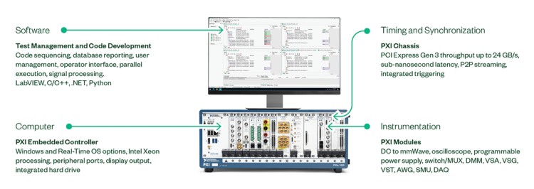
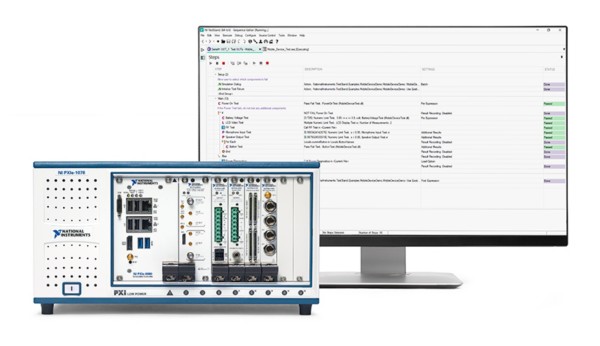
PXI systems are composed of three main hardware components: chassis, controller, and peripheral modules. The hardware systems are driven by software, often with individual portions of LabVIEW, C/C++, .NET, or Python code being organized by test management software (for example, TestStand).
Figure 2: A PXI system includes a chassis, controller, instrumentation, and software.
Contents
Chassis
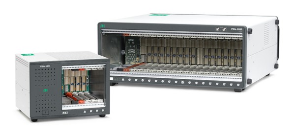
The PXI chassis is the backbone of a PXI system and compares to the mechanical enclosure and motherboard of a desktop PC. It provides power, cooling, and a communication bus to the system, and supports multiple instrumentation modules within the same enclosure. PXI uses commercial PC-based PCI and PCI Express bus technology while combining rugged CompactPCI modular packaging, as well as key timing and synchronization features. Chassis range in size from four to 18 slots to fit the needs of any application, whether its intentions are to be a portable, a benchtop, a rack-mount, or an embedded system.
Figure 3: NI PXI chassis vary in size from four to 18 slots.
PCI and PCI Express Communication
The PCI bus gained adoption as a mainstream computer bus in the mid-1990s as a parallel bus with a theoretical maximum of 132 MB/s shared bandwidth. PCI Express was introduced in 2003 as an improvement to the PCI standard. The new standard replaced the shared bus used for PCI with a shared switch, which gives each device its own direct access to the bus.
Unlike PCI, which divides bandwidth between all devices on the bus, PCI Express provides each device with its own dedicated data pipeline. Data is sent serially in packets through pairs of transmit-and-receive signals called lanes, which enable 250 MB/s theoretical bandwidth per direction, per lane for PCI Express 1.0. Since the introduction of PCI Express, the standard has continued to evolve to allow faster data rates while maintaining backward compatibility. PCI Express 2.0 doubles the per-lane theoretical bandwidth to 500 MB/s per direction, and PCI Express 3.0 doubles this again to 1 GB/s per direction, per lane. Multiple lanes can also be grouped together into x2 (“by two”), x4, x8, x12, and x16 lane widths to further increase bandwidth capabilities.
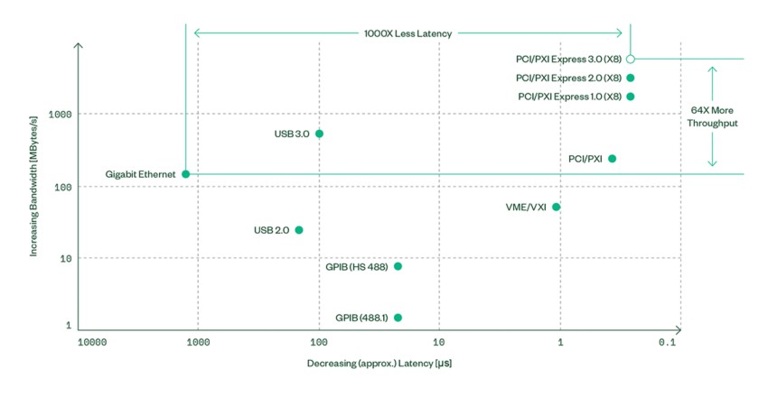
Figure 4: PCI Express provides a high data throughput and low communication latency bus, ideal for test and measurement applications.
Equivalently, the PXI Express standard evolved from the PXI standard to incorporate the PCI Express bus. This increased bandwidth allows PXI Express to meet even more application needs like high-speed digitizer data streaming to disk, highspeed digital protocol analysis, and large-channel-count DAQ systems for structural and acoustic test.
Because the PXI Express backplane integrates PCI Express while still preserving compatibility with PXI modules, users benefit from increased bandwidth while maintaining backward compatibility with legacy PXI systems. PXI Express specifies PXI Express hybrid slots to deliver signals for both PCI and PCI Express. With PCI Express electrical lines connecting the system slot controller to the hybrid slots of the backplane, PXI Express provides a high-bandwidth path from the controller to backplane slots. Using a PCI Express-to-PCI bridge, PXI Express provides PCI signaling to all PXI and PXI Express slots to ensure compatibility with hybrid-compatible PXI modules on the backplane. In doing so, these PXI Express hybrid slots provide backward compatibility that is not available with desktop PC card-edge connectors, in which a single slot cannot support both PCI and PCI Express signaling.
Timing and Synchronization
One of the key advantages of a PXI system is the integrated timing and synchronization. A PXI chassis incorporates a dedicated 10 MHz system reference clock, PXI trigger bus, star trigger bus, and slot-to-slot local bus to address the need for advanced timing and synchronization. These timing signals are dedicated signals in addition to the communication architecture. The 10 MHz clock within the chassis can be exported or replaced with a higher stability reference. This allows the sharing of the 10 MHz reference clock between multiple chassis and other instruments that can accept a 10 MHz reference. By sharing this 10 MHz reference, higher sample rate clocks can phase-lock loop (PLL) to the stable reference, improving the sample alignment of multiple PXI instruments. In addition to the reference clock, PXI provides eight transistor-transistor logic (TTL) lines as a trigger bus. This allows any module in the system to set a trigger that can be seen from any other module. Finally, the local bus provides a means to establish dedicated communication between adjacent modules.
Building on PXI capabilities, PXI Express also provides a 100 MHz differential system clock, differential signaling, and differential star triggers. By using differential clocking and synchronization, PXI Express systems benefit from increased noise immunity for instrumentation clocks and the ability to transmit at higher-frequency rates. PXI Express chassis provide these more advanced timing and synchronization capabilities in addition to all the standard PXI timing and synchronization signaling.
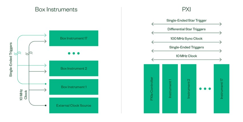
Figure 5: The timing and synchronization capabilities of PXI and PXI Express chassis provide the best-in-class integration of instrumentation and I/O modules.
In addition to the signal-based methods of synchronizing PXI and PXI Express, these systems can also leverage synchronization methods using absolute time. A variety of sources including GPS, IEEE 1588, or IRIG can provide absolute time with the use of an additional timing module. These protocols transmit time information in a packet so systems can correlate their time. PXI systems have been deployed over large distances without sharing physical clocks or triggers. Instead, they rely on sources such as GPS to synchronize their measurements.
Power and Cooling
The I/O and instrumentation modules that populate a PXI chassis vary in their amount of required power. NI PXI Express chassis provide at least 38.25 W of power and cooling to every peripheral slot; some chassis push slot cooling capacity even further and can provide 58 W or 82 W of cooling to a single slot. This extra power and cooling make advanced capabilities of high-performance modules, such as digitizers, high-speed digital I/O, and RF modules, possible in applications that may require continuous acquisition or high-speed testing. Chassis vary in total power, so it is always a best practice to perform a system-level power budget when configuring a new system.
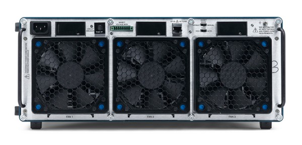
Figure 6: The PXIe-1085 24 GB/s chassis includes high-performance, field-replaceable fans.
Controller
As defined by the PXI Hardware Specification, all PXI chassis contain a system controller slot located in the leftmost slot of the chassis (slot 1). Controller options include remote control modules that allow PXI system control from a desktop, workstation, server, or laptop computer as well as high-performance embedded controllers with either a Microsoft OS (Windows 7/10) or a real-time OS (LabVIEW Real-Time).
PXI Embedded Controllers
PXI embedded controllers eliminate the need for an external PC and provide a high-performance, yet compact in-chassis embedded computer solution for your PXI or PXI Express measurement system. These embedded controllers have extended temperature, shock, and vibration specifications and come with an extensive feature list such as the latest integrated CPUs, hard drive, memory, Ethernet, video, serial, USB, and other peripherals. By providing these peripherals on the controller’s front panel, overall system cost is minimized because you don’t need to purchase individual PXI or PXI Express cards to gain similar functionality. The controller comes pre-configured with LabVIEW Real-Time or Microsoft Windows and all the device drivers pre-installed. NI’s embedded controllers also have managed life cycles and offer vendor support to ensure test system longevity and compatibility with the PXI ecosystem.
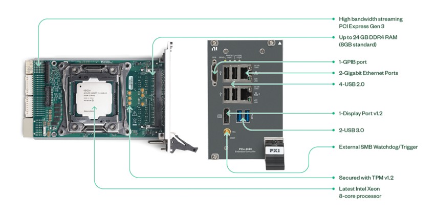
PXI embedded controllers are typically built using standard PC components in a small PXI package. Performance benchmarking done by NI R&D also ensures the development of controllers that are optimized for test and measurement applications to guarantee that code and algorithms run faster. For example, the PXIe-8880 has a 2.3 GHz eight-core Intel Xeon E5-2618L v3 processor (3.4 GHz maximum in single-core, Turbo Boost mode), up to 24 GB of DDR4 RAM, solid-state drive, two Gigabit Ethernet ports, SMB trigger, and standard PC peripherals like two USB 3.0 ports, four USB 2.0 ports, DisplayPort, and GPIB.
When NI releases a new PXI embedded controller, it offers the controller shortly after major computer manufacturers like Dell or HP release computers featuring the same high-performance embedded mobile processor. Because NI has been in the business of releasing PXI embedded controllers for more than 15 years, the company has developed a close working relationship with key processor manufacturers such as Intel and Advanced Micro Devices (AMD). For example, NI is an associate member of the Intel Embedded Alliance, which offers access to the latest Intel product roadmaps and samples.
Figura 7: The PXIe-8880 embedded controller, featuring the eight-core Intel Xeon E5 processor, is ideal for high-performance, high-throughput, and computationally intensive test and measurement applications.
In addition to computing performance, I/O bandwidth plays a critical role in designing instrumentation systems. As modern test and measurement systems become more complex, there is a growing need to exchange more and more data between the instruments and the system controller. With the introduction of PCI Express and PXI Express, NI embedded controllers have met this need and now deliver up to 24 GB/s of system bandwidth to the PXI Express chassis backplane.
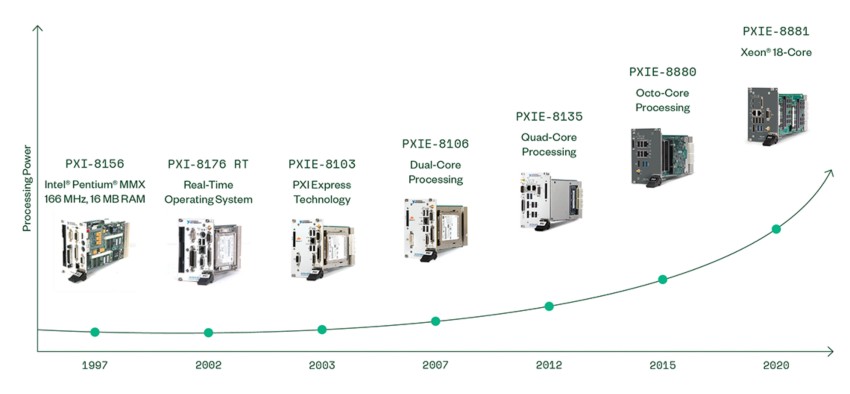
Figure 8: NI has continued to deliver the latest and most powerful processing technology to the PXI platform for the last 20 years.
Rack-Mount Controllers
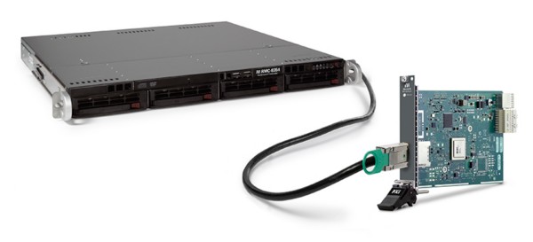
To provide an alternative computing and control option, NI offers external 1U rack-mount controllers. They feature high-performance multicore processors for intensive computation and multiple removable hard drives for high data storage capacity and high-speed streaming to disk. These controllers are designed to be used with MXI-Express and MXI-4 remote controllers for interfacing to PXI or PXI Express chassis. In this configuration, the PXI/PXI Express devices in the PXI system appear as local PCI/PCI Express devices in the rack-mount controller.
Figure 9: Rack-mount controllers with MXI-Express or MXI-4 remote controllers can be used to control PXI or PXI Express chassis.
PC Control of PXI
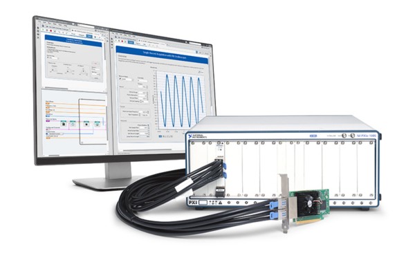
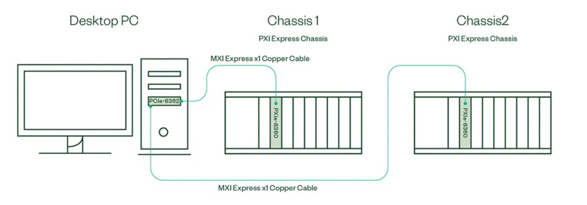
Through MXI-Express technology, PXI Remote Control Modules provide a simple, transparent connection between a host machine, like a desktop PC, and the PXI chassis and instruments. During start-up, the computer recognizes all peripheral modules in the PXI system as PCI boards, allowing further interaction with these devices through the controller. PC control of PXI consists of a PCI/PCI Express board in your computer and a PXI/PXI Express module in slot one of your PXI system, connected by a copper or fiber-optic cable. Copper cables offer higher data throughput capability, but are generally shorter (1 to 10 meters), while fiber-optic cables are available in much longer options (up to 100 meters), but may have lower data throughput capability. Most PCs are immediately compatible with PXI remote control solutions. Furthermore, compatibility with MXI-Express devices is ext ended to even more PCs through NI's MXI-Express Bios Compatibility Software.
Laptop Control of PXI
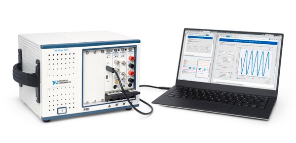
You can equivalently control a PXI Express system from a laptop computer using the PXIe-8301 remote control module from National Instruments. Laptop control of PXI Express consists of a PXI Express module in slot one of your chassis and a Thunderbolt 3™ cable connected to your laptop.
Figure 10: Remote control modules enable desktop control of one or more PXI chassis.
Figure 11: The PXIe-8301 remote control module is ideal for ultra-portable applications.
Multichassis Configurations
Multichassis configurations allow two or more PXI chassis to be managed by a single master controller. As a unified system, multiple chassis can take advantage of benefits such as cross-chassis synchronization, separation of instrument types to optimize data throughput, and peer-to-peer transfers between instruments in separate chassis.
The most common method of forming a multichassis system is through daisy chaining. A daisy-chain topology consists of one or more slave (downstream) chassis connected in series to a master (upstream) chassis that is controlled through a PC or PXI embedded controller. When using a daisy-chain topology, each slave chassis is visible to and controllable by the host machine.
Figure 12: A PXIe-8364 host interface module is placed in a peripheral slot of the master chassis containing an embedded controller. An additional chassis is daisy chained by connecting the PXIe-8364 to a PXIe-8360 in the system controller slot of the slave chassis. Additional modules may be used to daisy chain up to eight chassis.
While the above solution requires an additional module in a peripheral slot for daisy chaining, some PXI Remote Control Modules contain built-in daisy-chaining capability through the inclusion of two ports—one for an upstream connection and one for a downstream connection.
Figure 13: A desktop PC with a PCIe-8375 is connected to a master PXI Express chassis through a PXIe-8375 remote control module. The PXIe-8375 features an additional port for daisy chaining, requiring only an additional PXIe-8375. The last downstream chassis in this system will have an unused port.
Some host interface cards contain two downstream ports, allowing for a star topology. Rather than connecting two slave chassis in series (daisy chain), the star topology connects two slave chassis in parallel, allowing each chassis to communicate directly to the host rather than through an intermediary chassis.
Figure 14: The PCIe-8362 host interface card contains two MXI-Express connections, allowing two PXI Express chassis to be controlled through a desktop PC using a star topology.
Peripheral Modules
NI offers more than 600 different PXI modules. Because PXI is an open industry standard, nearly 1,500 products are available from more than 70 different instrument vendors. In addition, since PXI is directly compatible with CompactPCI, you can use any 3U CompactPCI module in a PXI system as well.
A common misconception regarding the small PXI footprint is that this space savings comes at the cost of performance.
It is important to understand that the PXI platform can offer this space savings not by lowering performance but by modularizing the system. Every traditional boxed instrument requires a separate processing circuitry system, display, and physical interface. For PXI-based instrumentation systems, these functions are designated to specific components shared among multiple instruments. A PXI embedded controller acts like a central processing and control hub for all the different instruments in the PXI chassis. It also provides a human interface through its connectivity to external peripherals such as a video monitor, keyboard, and mouse.
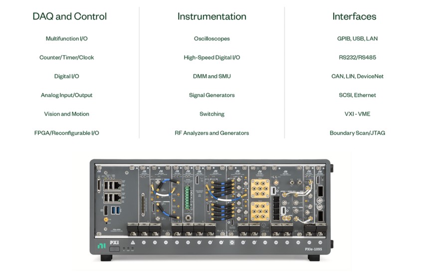
Figure 15: NI offers over 600 different PXI modules.
Software running on the embedded controller interacts with the different PXI instruments to define the actual functionality of the test system. With these standard functions designated to an embedded controller that offers state-of-the-art performance, PXI instruments need to contain only the actual instrumentation circuitry, which provides effective performance in a small footprint.
Software
The development and operation of a Windows-based PXI or PXI Express system is no different from that of a standard Windows-based PC. Therefore, you do not have to rewrite existing application software or learn new programming techniques when moving between PC and PXI-based systems. Using PXI, you can reduce your development time and quickly automate your instruments by using G in LabVIEW, an intuitive graphical programming language that is the industry standard for test, or NI LabWindows™/CVI for C development. You can also use other programming languages such as those that are part of Visual Studio .NET, Visual Basic, Python, and C/C++. In addition, PXI controllers can run applications developed with test management software such as TestStand. Test management software includes not only a test executive, but also a fully featured test architecture that provides you the flexibility to customize behavior to meet specific needs like sequencing, branching/looping, report generation, and database integration. Test management software along with PXI modular instrumentation provides an integrated solution that can both simplify test development and reduce maintenance for long-term success.
As an alternative to Windows-based systems, you can use a real-time software architecture for time-critical applications requiring deterministic loop rates and headless operation (no keyboard, mouse, or monitor). Real-time OSs help you prioritize tasks so that the most critical task always takes control of the processor, reducing jitter. You can simplify the development of real-time systems by using real-time versions of industry-standard development environments such as the LabVIEW Real-Time and LabWindows/CVI Real-Time modules. Engineers building dynamic or hardware-in-the-loop PXI test systems can use real-time testing software such as VeriStand to further reduce development time.
Figure 16: TestStand manages a PXI system’s test code regardless of the programming language used.
