Simplify Your DMM: Top Five Tools and Tips
Overview
Contents
- Basic Configuration and Calibration
- Interactive Control and Debugging
- Automated Measurements and Switching
- Complete Hardware Control
- Test System Management
- Conclusion
- Additional Resources
Basic Configuration and Calibration
When developing an automated test system, you must verify that the hardware in your system is identified, functional, calibrated, and ready to go.
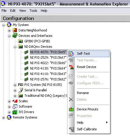
Like all NI hardware, NI DMMs include Measurement & Automation Explorer (MAX) to assist you with these essential configuration tasks. With this utility, you can identify all DMMs, switches, and any other measurement instruments in the same simple window; test or reset them as necessary; and access relevant help and connectivity documentation.
Figure 1. Measurement & Automation Explorer (MAX) Options for NI DMMs
Interactive Control and Debugging
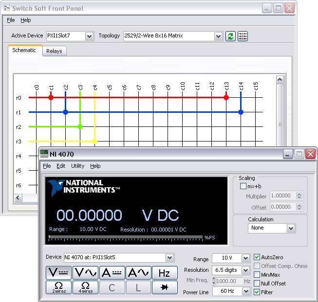
Another important step during the development of an automated test system is the initial testing and debugging of signal connections. During this phase, you make simple measurements to prove that instruments are properly connected and functioning and that measurement results are accurate. For this stage, NI offers soft front panels (SFPs) - stand-alone software applications that provide a simple way to monitor and control hardware interactively. Figure 3 shows the NI-SWITCH and NI-DMM soft front panels.
Figure 3. NI-SWITCH (top) and NI-DMM (bottom) Soft Front Panels
As you can see from Figure 3, you can use the NI-DMM SFP to the active DMM device to control the measurement type, range, resolution, and various other parameters. Similarly, you can use the NI-SWITCH SFP to identify a switch module, configure the topology, and make individual relay connections.
Tip - Checking Individual Relay States and Counts
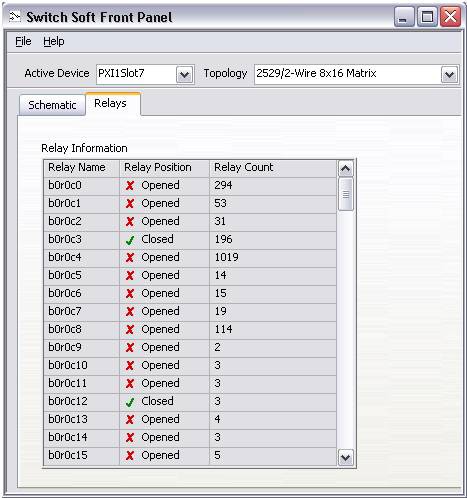
Because mechanical relays have a finite lifetime (usually on the order of 10^5 cycles or above), maintaining an accurate count of the number of relays can be important to ensuring test system functionality. Many NI switch modules offer onboard relay count tracking, which you can check via the NI-SWITCH SFP. Figure 4 shows the relay counts of a matrix switch as seen in the NI-SWITCH SFP.
Figure 4. Relay State and Count in the NI-SWITCH Soft Front Panel
Additionally, you can query relay usage programmatically via the NI-SWITCH API in NI LabVIEW software or any other supported programming language. Using programmatic calls, you can set a threshold at which a user is alerted when a certain number of relay cycles have completed, indicating that it is time to check the health of the switch contacts.
Read how to programmatically track relay usage on NI switches.
Automated Measurements and Switching
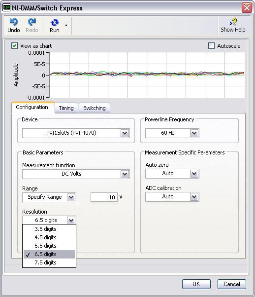
Once you have connected the components in an automated test system and have verified the necessary measurements, the next step is to automate the measurements programmatically. While this task can typically take a test developer days or weeks of work, the NI-DMM/Switch Express VI in LabVIEW makes it simple to perform automated measurements and switching within minutes. Figure 5 shows the main configuration tab, which you can use to select the DMM device and control all standard measurement settings.
Figure 5. NI-DMM/Switch Express VI Configuration Window in LabVIEW
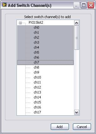
Once you have appropriately configured the DMM, you can add switch channels from any NI multiplexer on the switching tab by choosing the one or more switch devices and selecting the desired channels from each.
Figure 6. Adding Switch Channels in the NI-DMM/Switch Express VI
Once you have configured both the DMM measurements and switch channels, you can test the data in the Express VI itself and save the configuration with the OK button so you can use the data from the LabVIEW block diagram.
Tip - Advanced Triggering Configuration
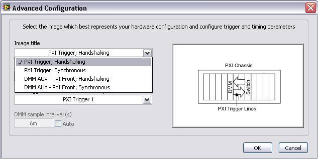
To optimize the speed of switching and measurements, NI DMMs and multiplexers in the PXI form factor automatically send triggers over the PXI backplane. This removes the need for host software interaction when scanning many channels of a multiplexer, thereby improving test speed. For more explicit control over this interaction, you can modify this trigger handshaking with the NI-DMM/Switch Express VI and directly specify the exact trigger lines you are using.
Figure 7. Advanced Triggering Options for DMM/Switch Synchronization in the NI-DMM/Switch Express VI
Complete Hardware Control
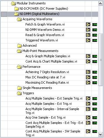
While the NI-DMM/Switch Express VI is ideal for most automated test systems, you may need to have lower-level control over test hardware configuration and execution. You can accomplish this with the application programming interface (API) for a respective instrument, such as NI-DMM or NI-SWITCH. To provide easy access to the full functionality of NI hardware via these APIs, all NI products are shipped with prebuilt example programs that demonstrate particular features and implementations of the relevant API. Figure 8 shows just a few of the prebuilt example programs for the NI-DMM API as seen in the LabVIEW Example Finder.
Figure 8. NI-DMM Example Programs for LabVIEW in the LabVIEW Example Finder
You can access these examples by choosing the Help>>Find Examples... from the toolbar in LabVIEW. The NI-DMM and NI-SWITCH APIs also offer support and example programs for NI LabWindows™/CVI, Microsoft Visual C++, and Microsoft Visual Basic, which you can access by going to Start>>Program Files>>National Instruments>>NI-DMM>>Examples in Windows.
Test System Management
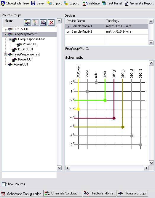
Finally, depending on the size and complexity of the automated test system under development, higher-level tools for test configuration and management can be vital to system success. In particular, systems with high-channel counts incorporating multiple switch modules can be very difficult to program, maintain, and debug. To make this process easier and more repeatable, you can use NI Switch Executive to configure and manage your switching setups. Figure 9 shows an example configuration that has multiple switches connected to multiple instruments and multiple devices under test (DUTs).
Figure 9. NI Switch Executive Main Window Showing Schematic Configuration
Learn more about NI Switch Executive.
Tip - Using Switch Executive with NI TestStand
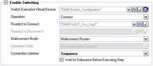
Complex automated test systems often incorporate test management software such as NI TestStand to control the sequence, execution, and reporting of tests. Because switching is a vital part of test sequencing in larger systems, you can call NI Switch Executive from within the NI TestStand environment to control your switch hardware on a per-test basis. This means you can write each piece of test code separately from any switch configuration, so you can repurpose and modify tests more easily.
Figure 10. NI Switch Executive Integration for an NI TestStand Action Step Type
Conclusion
When choosing a DMM for an automated test system, consider your development strategy in addition to your hardware specifications. National Instruments DMMs are specifically designed for use in automated test systems. As a result, they provide a variety of tools that make programming and automation faster, easier, and more reliable.
Additional Resources
The mark LabWindows is used under a license from Microsoft Corporation. Windows is a registered trademark of Microsoft Corporation in the United States and other countries.
