Buffered Event Counting
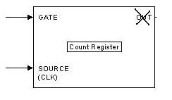
Event Counting is the most fundamental of all counter operations where the focus is on measuring the source signal. It basically counts the number of active edges that have arrived on the source of the counter by polling the count register with software commands. Buffered Event Counting is thus a form of Event Counting where the gate acts as a control signal to latch the current register count value into the PC memory. This measurement is sometimes referred to as time-stamping because it allows one to measure the elapse time between sequential events occurring on the gate. Figure 1 shows the basic counter chip components used for buffered event counting.
Figure 1. Counter Chip
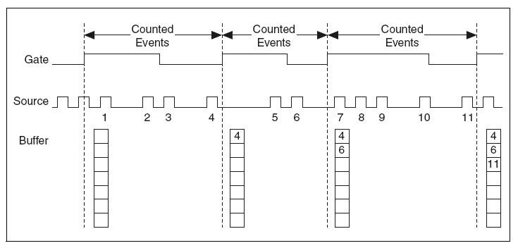
It uses both the source and gate of a counter for its operation. The active edges on the gate of a counter is used to latch the current count register value in a hardware register which is then transferred via Direct Memory access (DMA) or interrupt to preallocated PC memory or software buffer. The software buffer can be finite or circular for continuous operations. Once in the software buffer, the values can then be read in LabVIEW. The gate signal acts much like a sample clock, sampling the current value of the count register. Figure 2 illustrates the transfer of count register to memory
Figure 2. Buffered Event Counting
The control flow for programming buffered events requires that a buffer is configured. A buffer can be configured in DAQmx using the DAQmx Timing function located on the function palette under NI Measurement à DAQmx.
Since the function is polymorphic, it is important to note that the property to modify is the “Sample Clock”. With the DAQmx Timing function, the buffer size, the buffer mode, the sample clock source (gate pin) and the sample clock polarity (gate polarity) can be set as shown in Figure 3.
Figure 3. Buffer Configuration with DAQmx Timing function
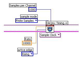
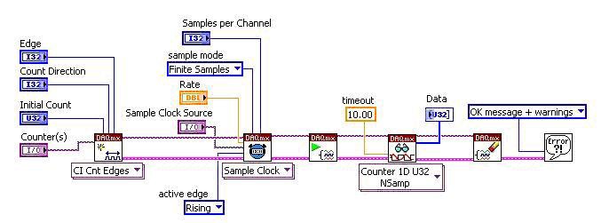
The buffered can be configured for finite or continuous acquisition. In Finite Buffer Event Counting, the sample Mode is set to “Finite Sample”, to copy data from the preallocated PC memory to the application development environment (ADE) memory. Figure 4 shows a sample LabVIEW program that performs finite buffer event counting.
Figure 4. Finite Buffered Event Counting
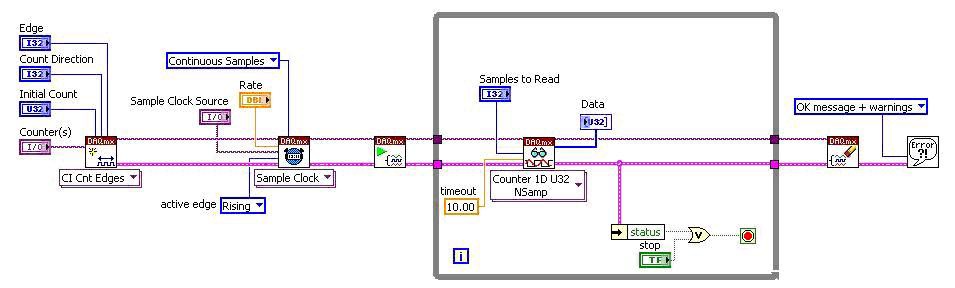
Continuous buffer event counting is similar to Finite Buffered Event Counting as shown in Figure 5, except that the buffer is read in a loop. Similarly, the Sample Mode is configured as “Continuous Samples. A continuously buffered input is also called a circular or double buffered input.
Figure 5. Continuous Buffered Event Counting