Best Practices for Using Multiple Network Interfaces (NICs) with NI Products
Overview
Contents
- Background: Ethernet Networking Concepts
- Guidelines for Configuring Multi-NIC Systems
- Example Scenarios
- Additional Resources
Background: Ethernet Networking Concepts
Before explaining best practices for configuring controllers with multiple NICs, it is necessary to understand some basic concepts related to Ethernet networking. This section explains how individual NICs are addressed, how packets are routed on Ethernet networks, and what a typical Ethernet packet transfer looks like.
If you are already familiar with these concepts or are not concerned about the "why" behind the recommendations in this paper, then you can skip to the Guidelines for Configuring Multi-NIC Systems section.
Data Link Layer: MAC Addressing
Just like a home or business address must be specified in order to send a piece of postal mail, every port on every Ethernet adapter is assigned a unique address called a Medium Access Control (MAC) address by the manufacturer. MAC addresses consist of 48 bits, and are commonly expressed in groups of 2 hexadecimal digits (e.g. 01:23:45:67:89:ab). The MAC address or addresses for a specific Ethernet adapter are commonly printed on a label on the device itself, and are also accessible via operating system networking settings.
When Ethernet data is sent between two computers, it is sent in small pieces called "packets", and those packets contain the MAC address of the receiving interface. Each interface is continually listening for packets sent to its unique address.
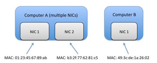
Figure 1: Each network interface controller (NIC) in a computer has a unique medium access control (MAC) address. If multiple NICs are installed in one computer, they each have their own MAC addresses.
Internet Layer Addressing
If every computer in the world were connected to one large wire and knew every other computer's MAC address, then no further addressing schemes would be required. However, this is impractical for several reasons. First, with such a large shared connection packet collisions would occur frequently, causing communication to be unreliable. Second, storing the address of every other computer on the planet on each machine would require a large amount of memory, and is not a good strategy due to the constant addition of new devices.
IP Addresses (IPv4)
Clearly, a different scheme of addressing is needed to enable computers to communicate with each other via Ethernet. In practice, users can assign one or more Internet Protocol (IP) addresses to each MAC address, and set these IP addresses up in such a way that most network traffic occurs in small "pools" rather than across a wider group of machines. In practice, IP addresses are typically specified by a 32-bit value, and are commonly written as four groups of 3-digit decimal values (e.g. 192.168.100.100). Consider a network with 10 computers configured such that the computers have IP addresses ranging from 192.168.100.0 to 192.168.100.9. If all machines follow a rule where all addresses with format 192.168.100.xxx are assumed to be inside the internal network, then it is easy to tell whether communicating with a given IP address requires accessing some other network or not.
Sample rule: all interfaces with IP addresses in the range 192.168.100.0 to 192.168.100.255 are inside of the local network, and interfaces with other addresses are outside.
| IP Address | Inside or Outside Local Network? (following the sample rule) |
| 192.168.100.6 | Inside |
| 192.168.100.104 | Inside |
| 192.169.100.100 | Outside |
| 192.169.101.255 | Outside |
Table 1: Since IP addresses can be assigned to individual NICs by the user, it is possible to assign similar IP addresses to a group of interfaces and then easily determine whether a given IP address is inside or outside of the local network.
This simple idea has significant benefits. Whereas MAC addresses do not typically follow a pattern in a given set of machines (they are randomly distributed by vendor), since IP addresses are user-configurable they can be set up to follow a logical, hierarchical pattern. Using this pattern, small groups of computers can communicate with each other with only local traffic, therefore reducing data collisions in the larger network. In addition, since there are more than 2^32 connected Ethernet devices on the planet, IP addresses can be reused across multiple smaller networks while those machines are still accessible via a process called Network Address Translation (NAT). A detailed discussion of NAT is beyond the scope of this tutorial.
When configuring IP addresses, you are likely to run across addresses of the form 10.x.x.x, 192.168.x.x, or 172.x.x.x. Each of these ranges have been specially designated for private network use, so you can be sure that no other public server (e.g. google.com) will use the same IP address if you use one of these.
It should be noted that the information in this section pertains to the most commonly used version of the Internet Protocol called IPv4. The next version of the Internet Protocol, IPv6, uses 128-bit addresses but is not widely used today (although adoption is expected to grow in the next several years).
Subnet Masks
So, when looking at an IP address to send data to, how does a given computer decide if it is inside of the local network, or whether it will rely accessing an outside network? In other words, if we want computers to follow a rule as was the case with the example in the previous section, how is that rule specified?
The key component here is the subnet mask, a group of 32 bits expressed in 4 groups of numbers just like the IP address (e.g. 255.255.255.192). A binary 1 value in one of the 32 bit positions means that if the IP address bit is different in this position between the sender and receiver, then Ethernet packets must be routed to an outside network. On the contrary, a binary zero in a given position means that if the IP address bit is different then it does not matter; if all other bits are the same between the sender and receiver's IP address then the receiver is assumed to be on the same local network.
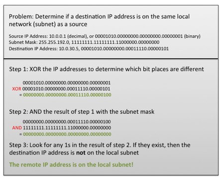
Figure 2: Subnet masks provide a way to specify the "rule" for which IP addresses are included in a local network and which fall outside of the local network.
Gateways and Default Gateways
How are Ethernet packets passed between local and outside networks? This task is typically performed by a device called a router, that is also often referred to as a network gateway (in this tutorial the two terms will be used interchangeably). For each Ethernet adapter connected to a computer, the user often specifies an IP address, subnet mask, and default gateway. The default gateway is the address of the router that should be used when packets must be sent outside of the local network.
ARP Requests
At this point, note that at the lowest level, every single Ethernet packet that is sent must be sent to a MAC address. IP addresses provide some advantages including the use of subnets, but keep in mind that simply knowing the IP address of a remote computer's interface is not enough information to ensure that a packet reaches that computer. For example, to communicate between two computers on remote networks it may be necessary to pass through several routers. At a low-level, one packet must be sent between the sending computer and the first router, then another packet from the first router to the next, and so forth until the final packet finally reaches the destination computer. For the packet to be sent between each link, knowing the MAC address of the receiving router or computer's interface is critical.
Imagine starting with an IP address of a destination computer on the local network: how does the originating computer obtain the correct MAC address to send packets to? The Address Resolution Protocol (ARP) is used for this. Continuing with the example, the sending computer will send a special type of broadcast message called an ARP request on the local network (requesting the MAC address for a certain IP address). All Ethernet devices on the network are continually listening for these special requests, and will respond back to the sender with their MAC address if they match the IP address specified. Once the MAC address is received by the sending computer, that computer will usually store the MAC address / IP address pair in a cache table for later usage. This prevents the continual need to send ARP requests for the same destination interface.
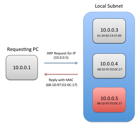
Figure 3: For a computer to send data to a remote Ethernet interface, it must know the MAC address of that interface. In the case that the MAC address is not known, a computer can send an Address Resolution Protocol (ARP) request to a specified IP address, and the destination machine will reply back with its MAC address.
If a router on the network knows that the IP requested is external to the local network, then it can also respond to the ARP request with its own MAC address. This is called "proxy ARP".
Summary: Anatomy of an Ethernet Packet Transfer
Let us walk through the (simplified) process of sending a single Ethernet packet from a source PC to a destination PC. We will assume that the Source PC contains multiple Ethernet interfaces.
- An Ethernet packet is ready to be sent by the source machine (this could be associated with a specific application or OS process). The packet contains information about the IP address of the receiver (this may have been obtained from a Domain Name Service (DNS) server).
- If there is already a cached ARP entry containing the MAC address corresponding to the receiver's IP address, then proceed to step 4.
- The Sender looks at the IP address of the packet, and the subnet mask of its Ethernet interfaces.
- If the IP address falls within the subnet of a specific interface, then an ARP request is sent from that interface.
- If the IP address falls outside of the subnet of any interfaces, then the sender looks at the default gateway entry for each interface.
- If there is only one default gateway entry for all interfaces, then use its MAC address as contained in the ARP table or send a new ARP request to find the MAC address of the gateway.
- If there are multiple default gateway entries, then use the one with the lowest metric (determined by several factors depending on the OS used). Find its MAC address in the ARP table, or send a new ARP request to find the MAC address of the gateway.
- If there are no default gateway entries, send an ARP request on one or more interfaces to see if a gateway responds with its own MAC (proxy ARP).
- Send the Ethernet packet using the MAC address from the ARP cache or ARP request. If the ARP request does not produce a result, then the packet is not deliverable. If the receiver is on a remote subnet, then the packet is sent to a router and it is the router's job to send the packet over the next link so that it ultimately reaches the receiver.
Guidelines for Configuring Multi-NIC Systems
When working with a computer that features multiple network interfaces, you must pay closer attention to networking settings to avoid difficult-to-debug connectivity problems. Follow these guidelines to ensure the best operation of your multi-NIC system. This includes any PC or embedded controller running a desktop OS and LabVIEW, as well as any LabVIEW Real-Time target with multiple Ethernet interfaces.
Rule 1: Be Careful About Automatic IP Assignment (via DHCP or link-local addressing)
Most OSs are configured by default to obtain TCP/IP settings (IP address, subnet mask, and default gateway) automatically using a Dynamic Host Configuration Protocol (DHCP) server. If no DHCP server is found, then it is common practice for OSs to assign an IP address in the 169.254.x.x range, which is referred to as a link-local IP address.
Make sure that you are familiar with the DHCP server(s) on your network, and what IP address ranges and subnets they make use of. Likewise, make sure that you know if any adapters in your computer use DHCP and no DHCP server is on the network, resulting in the use of a 169.254.x.x address. If you are not familiar with the automatic IP assignment details for your network, then there is a much higher chance that you will break Rule 2 or Rule 3 below.
If possible given your network configuration, it is best to manually specify IP settings for each NIC in your multi-NIC PC. However, if you are on a network with other DHCP clients, using DHCP may be unavoidable.
Rule 2: Avoid Assigning Multiple NICs in the Same Computer to the Same Subnet
Using multiple NICs on the same subnet is the #1 cause of connectivity issues on multi-NIC systems. While some OSs may be able to gracefully handle the presence of multiple NICs on one subnet, others may mistakenly attempt to send packets out of the wrong interface. You can remedy this issue by statically assigning one NIC (and the other networked computers attached to that NIC) to the 192.168.x.x range with subnet mask 255.255.0.0, and another NIC on the 10.0.x.x range with subnet mask 255.255.0.0. Note that this is just one possible configuration, any combination of two or more different subnets will work. It is recommended that you use one of the designated private IP address ranges to avoid conflicts with public servers on the internet.
In practice, there is rarely a good reason to use multiple NICs on the same subnet. One advanced configuration that warrants this setup is using multiple adapters to increase bandwidth is called adapter teaming, however this configuration is beyond the scope of this paper.
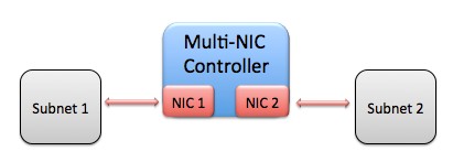
Figure 4: When configuring a controller with multiple NICs, each NIC should communicate with a different subnet. Configuring two or more NICs on the same subnet may cause communication problems.
One of the most common scenarios resulting in multiple NICs being assigned to the same subnet is when both a wired and wireless interface are used to connect to the same network. Once again, while some OSs may handle this case gracefully, it is a best practice to either configure the wired and wireless networks to exist on different subnets or to disable one network interface when using the other.
Rule 3: Avoid Specifying a Default Gateway for More Than One NIC
When a destination IP address does not fall within the subnet of any NIC, then a default gateway is used to relay packets to the outside network. If multiple default gateways exist, then packets may be routed to the wrong outside network, causing them to be undeliverable.
In most cases, you should be able to address all computers attached to a network interface on the same private subnet, and leave the default gateway blank for that interface. Typically only one NIC with a gateway to the internet or corporate network should have a default gateway address specified.
| NIC 1 Connected to Corporate Network and Internet | NIC 2 Connected to Local Network |
| IP Address: 192.168.50.8 | IP Address: 10.0.3.7 |
| Subnet Mask: 255.255.0.0 | Subnet Mask:255.255.255.0 |
| Default Gateway:192.168.1.1 | Default Gateway: 0.0.0.0 (or blank) |
Table 2: When choosing TCP/IP settings for a multi-NIC system, it is a best practice to specify a default gateway for only one adapter. This is also true when one of the default gateway addresses is obtained via DHCP.
In other cases where gateways are attached to subnets that connect with different network interfaces, you can either manually specify network routes (this is an advanced practice) or leave the default gateway blank for all interfaces.
While it is more efficient to specify a default gateway on one interface (this avoids the need for an ARP on many packets transmitted to outside networks), leaving all default gateway entries blank can help avoid problems in networks with multiple gateways. However, this strategy will only work if network gateways support proxy ARP.
Example Scenarios
Case 1: Connecting to One Public and One Private Network
In this scenario, a host PC is connected to both a corporate network (via NIC #1) which allows internet access as well as a private network (via NIC #2) with several LabVIEW Real-Time targets. The corporate network is setup to assign a DHCP address in the range of 10.0.x.x with subnet mask 255.255.0.0 to NIC #1. The default gateway (router) address is 10.0.0.1.
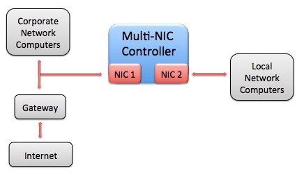
Figure 5: In this scenario, a multi-NIC controller is connected to both a corporate network (with internet access) and a local private network.
Following the guidelines above, we can configure NIC #2, attached to the private network, with a static IP outside of the 10.0.x.x subnet range. While it might be acceptable to use an address in the 10.1.x.x range, as it is in a different subnet, it is possible that other 10.x.x.x IP addresses are used for additional corporate servers, etc. Therefore, it is safer to use the 192.168.x.x range for the private network.
Since we are working with a small number of LabVIEW Real-Time targets in the private network, we can use a subnet mask of 255.255.255.0 and assign each a static IP address in the range 192.168.0.x; this will allow for up to 255 connected interfaces in the subnet. For simplicity, the IP address of the host computer (NIC #2) will be set to 192.168.0.1.
It is important to leave the default gateway blank on the NIC #2 settings for the host machine. In this way, only the NIC #1 default gateway will be used, which is what we want in order to access the internet from the host. In addition, the default gateway can be left blank on the LabVIEW Real-Time devices, as they should only be communicating within the local subnet (there are no gateways connected).
| NIC 1 Connected to Corporate Network and Internet | NIC 2 Connected to Local Private Network |
| IP Address: (DHCP) 10.0.x.x | IP Address: 192.168.0.1 |
| Subnet Mask: (DHCP) 255.255.0.0 | Subnet Mask: 255.255.255.0 |
| Default Gateway: (DHCP) 10.0.0.1 | Default Gateway: 0.0.0.0 (unspecified) |
Table 3: This table shows one possible IP address configuration for the system shown in Figure 5 above. Notice that the two NICs connect to different subnets, and that only one Default Gateway address is specified.
Case 2: Configuring an NI Real-Time Hypervisor System with Virtual Ethernet Connection (local development)
NI Real-Time Hypervisor systems run a host OS (Windows or Linux) alongside LabVIEW Real-Time simultaneously. Each physical NIC in these systems can be assigned to either the host OS or LabVIEW Real-Time, and a virtual NIC (emulated in software) is also presented to each OS to simplify inter-OS communication.
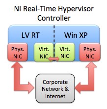
Figure 6: In this scenario, a Real-Time Hypervisor controller is running both Windows XP and LabVIEW Real-Time in parallel. Both OSs are connected to each other through a set of virtual NICs, and each OS has a physical NIC to connect to the corporate network & internet as well.
In this scenario we will work with a Real-Time Hypervisor system that has two physical NICs, and has the internal Virtual Ethernet connection enabled. One physical interface will be assigned to Windows XP, and the other to LabVIEW Real-Time. Therefore, each OS will have access to two NICs (the Virtual Ethernet connection and one physical connection). The Windows XP side of the hypervisor system will be used for LabVIEW Real-Time application development and deployment.
Assume that the physical connections are used to enable communication to the internet from either OS via a corporate network. The virtual interface will be used only for communication between LabVIEW Real-Time and Windows XP. The IP address of both physical adapters connected to the corporate network will be dictated via DHCP, and will be in the range 10.0.0.x with subnet mask 255.255.255.0. The gateway address is set to 10.0.0.1.
Following the guidelines above, we should set a static IP for each of the Virtual Ethernet adapters using a different subnet than is used with the physical adapter on each OS. Although other addresses in the 10.x.x.x range could be used, to be conservative we will set the IP addresses of the Windows XP and LabVIEW Real-Time adapters to 192.168.0.1 and 192.168.0.2 respectively. The subnet mask of each is set to 255.255.255.0.
Because we want both Windows XP and LabVIEW Real-Time to access the internet via the physical NICs, they should be the only adapters that have a default gateway set. Therefore, we will leave the default gateway entry for both Virtual Ethernet NICs empty. Note that each OS ultimately has only one default gateway specified.
| LV RT Physical NIC | LV RT Virtual NIC | Win XP Virtual NIC | Win XP Physical NIC |
| IP Address: (DHCP) 10.0.0.x | IP Address: 192.168.0.2 | IP Address: 192.168.0.1 | IP Address: (DHCP) 10.0.0.x |
| Subnet Mask: (DHCP) 255.255.255.0 | Subnet Mask: 255.255.255.0 | Subnet Mask: 255.255.255.0 | Subnet Mask: (DHCP) 255.255.255.0 |
| Default Gateway: (DHCP) 10.0.0.1 | Default Gateway: 0.0.0.0 (unspecified) | Default Gateway: 0.0.0.0 (unspecified) | Default Gateway: (DHCP) 10.0.0.1 |
Table 4: This table shows one possible IP address configuration for the system shown in Figure 6 above. Since there are two OSs running on a single hypervisor controller in this case, the important thing to note is that each OS connects to separate subnets with each NIC, and a maximum of one default gateway.
Case 3: Configuring an NI Real-Time Hypervisor System with Virtual Ethernet (remote development)
In this scenario, two physical NICs are also used in a Real-Time Hypervisor system with the Virtual Ethernet connection enabled as in Case 2 above. However, the physical NIC assigned to LabVIEW Real-Time will be used for deployment from a networked host PC rather than for internet access.
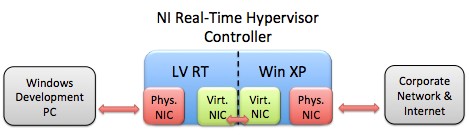
Figure 7: In this scenario, the LabVIEW Real-Time side of an NI Real-Time Hypervisor system is connected to a remote Windows PC for LabVIEW Real-Time application development.
The Windows physical adapter will still be assigned a DHCP address in the range 10.0.0.x with subnet mask 255.255.255.0. The Virtual Ethernet adapters on Windows XP and LabVIEW Real-Time will once again use static IP addresses of 192.168.0.1 and 192.168.0.2 respectively, with subnet masks of 255.255.255.0 and no default gateway.
To ensure that the physical NIC used with LabVIEW Real-Time is on a different subnet than the Virtual Ethernet NIC, we can use an IP address of the form 192.168.1.x with subnet mask 255.255.255.0. Therefore, the remote PC adapter and LabVIEW Real-Time adapter connected together can use static IP addresses of 192.168.1.1 and 192.168.1.2 respectively with subnet masks of 255.255.255.0. Once again, no default gateway is needed since neither adapter needs to access an outside network (no gateways are present on this subnet).
| Win Host NIC | LV RT Physical NIC | LV RT Virtual NIC | Win XP Virtual NIC | Win XP Physical NIC |
| IP Address: 192.168.1.1 | IP Address: 192.168.1.2 | IP Address: 192.168.0.2 | IP Address: 192.168.0.1 | IP Address: (DHCP) 10.0.0.x |
| Subnet Mask: 255.255.255.0 | Subnet Mask: 255.255.255.0 | Subnet Mask: 255.255.255.0 | Subnet Mask: 255.255.255.0 | Subnet Mask: (DHCP) 255.255.255.0 |
| Default Gateway: 0.0.0.0 (unspecified) | Default Gateway: 0.0.0.0 (unspecified) | Default Gateway: 0.0.0.0 (unspecified) | Default Gateway: 0.0.0.0 (unspecified) | Default Gateway: (DHCP) 10.0.0.1 |
Table 5: With a remote LabVIEW Real-Time development machine added to this scenario, IP address settings must be chosen such that the remote PC can connect with the LabVIEW Real-Time side of the hypervisor system.
Many other configurations are also possible, including using DHCP with the remote development PC and LabVIEW Real-Time target (to allow connection with the internet), or using additional NICs in the LabVIEW Real-Time target or remote host computer to connect to the internet.
Case 4: Connecting to Two Routed Networks (advanced)
One more advanced scenario involves configuring a computer (running only one OS this time) with two NICs that communicate with two local networks. Each network features a gateway that can be used to relay packets to additional outside networks.
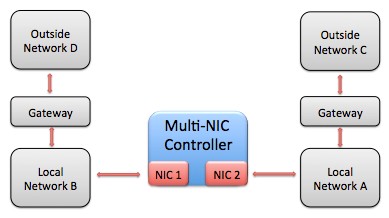
Figure 8: In this advanced scenario, a multi-NIC computer connects to two routed networks. This TCP/IP configuration is more difficult to set up, especially if the outside networks are not supersets of the local network subnets.
Imagine that local network A uses IP addresses of the form 10.0.0.x with subnet mask 255.255.255.0, and local network B uses IP addresses of the form 10.0.1.x with subnet mask 255.255.255.0. Local network A is connected via a gateway to outside network C, which uses IP addresses of the form 192.168.0.x with subnet mask 255.255.255.0. Likewise, local network B is connected to outside network D via a gateway, which uses IP addresses of the form 192.168.1.x with subnet mask 255.255.255.0.
The goal is for our multi-NIC PC to be able to access any of the networks. We can connect one NIC to local network A and assign the IP address 10.0.0.5 with subnet mask 255.255.255.0, and we can connect the second NIC to local network B and assign the IP address 10.0.1.5 with subnet mask 255.255.255.0. If any default gateway were assigned, then packets destined for the outside networks may be sent through the wrong gateway, and so this is undesirable.
To solve this problem, we can leave the default gateway entries blank for the two NICs and configure packet routing more manually in the OS. While all OSs are configured differently, most enable the manual addition of routes by the user, and these routes can be configured to persist across reboots of the system. Specifically, we need to add a route with IP address 192.168.0.x and subnet mask 255.255.255.0 to use the IP address of the gateway between networks A and C (e.g. 10.0.0.1). The same needs to be done with IP address 192.168.1.x and subnet mask 255.255.255.0 for the gateway between networks B and D (e.g. address 10.0.1.1).
| NIC 1 | NIC 2 |
| IP Address: 10.0.0.5 | IP Address: 10.0.1.5 |
| Subnet Mask: 255.255.255.0 | Subnet Mask:255.255.255.0 |
| Default Gateway: 0.0.0.0 (unspecified) | Default Gateway: 0.0.0.0 (unspecified) |
| Special Route: Use NIC 1 and gateway 10.0.0.1 to route to 192.168.0.x | Special Route: Use NIC 2 and gateway 10.0.1.1 to route to 192.168.1.x |
Table 6: While typically only one NIC in a controller will connect with a gateway (to a corporate network or the internet), more advanced configurations such as the one pictured in Figure 8 above may require special OS routing entries to function properly.
Additional routes may need to be added as the number of distinct subnets increases. In practice, most networks are set up to avoid the need for this complex configuration by ensuring that each computer is connected to only one gateway.