Creating a Camera File using the NI Camera File Generator
Overview
Contents
- Software Installation
- Find Default Camera Settings
- Selecting Camera Default Settings
- Configuring the Tap Geometry
- Enabling Power Over Camera Link (PoCL)
- Acquisition in Camera File Generator
- Camera Control in Camera File Generator
- Saving Camera File
- Additional Resources
Software Installation
Download the NI Camera File Generator here.
Note: If you are using Vision Acquisition Software 18.0 or newer, you will need to use the NI Camera File Generator 18.0, which is linked above. Version 3.0.1, which is used by older versions of software, is also available for download.
Once the installation is complete, go to the Start Menu find the folder National Instruments > Camera File Generator.
Find Default Camera Settings
Before you start creating your camera file, you will need to determine your camera’s default settings. The settings selected in the camera file determine how the frame grabber interprets the data coming from the camera. Therefore, in order to acquire successfully from your camera, you will need the settings used by the frame grabber and power-on settings of the camera to match for a seamless getting started experience.
We will be covering in a later section how to change camera’s settings if you do not want the default ones.
The default settings of a camera are usually listed in its user manual. If you cannot find that information easily you can use the vendor’s utility to look at the camera’s current settings. On power-up, those should be default.
Selecting Camera Default Settings
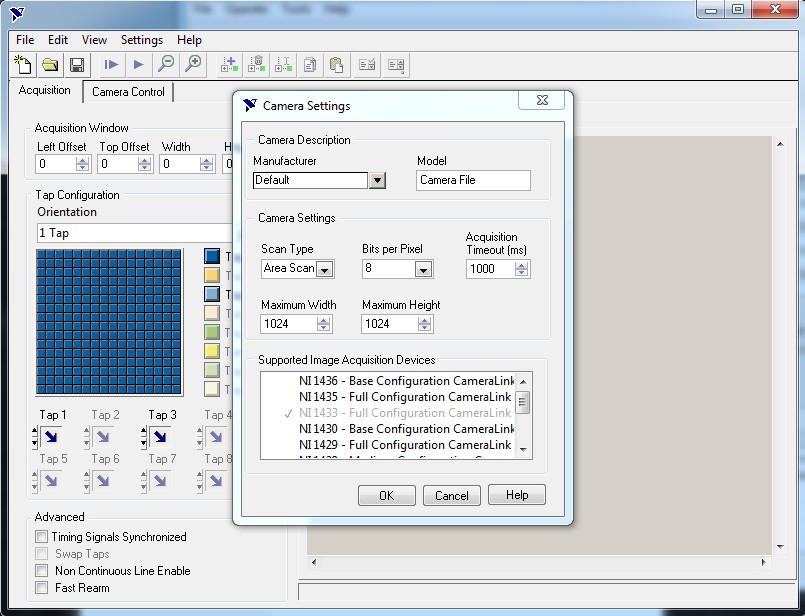
The main things you will need to specify in the camera file to start acquiring are the following:
- Manufacturer: Type in the name of Manufacturer and Model. This will be the name of your camera file so make sure is it specific.
- Camera Settings:
Scan Type: Area Scan or Line Scan camera.
Bits per Pixel: Default Pixel Depth supported by the camera. This information can be found in the camera’s manual or using the vendor’s utility software. A later section will explain how to use attributes to modify the camera’s bit depth.
Maximum Width and Maximum Height: Resolution of the camera can be found in the Camera’s manual or datasheet. A later section will explain how to use attributes to modify the camera’s image size to support binning for example.
Supported Image Acquisition Devices: Select the Frame Grabbers you would like to use this camera with. Make sure that your Frame Grabber is compatible with your camera
As an example, let’s create a camera file for the Baumer HXC20 camera.
We already know it’s an area scan camera, so let’s find the default bits per pixel and maximum width and height of the camera in the camera’s user manual:
Bits per pixel:
The default bits per pixel is Mono8 which stands for Monochrome 8 bit.
Default Width and Height should be listed in the datasheet:
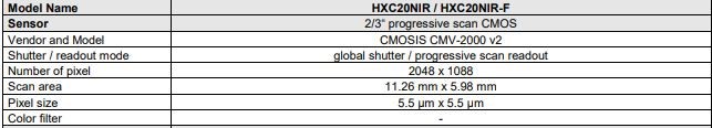
With this information, we can fill in the camera settings:
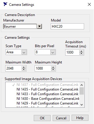
Press OK to choose your tap geometry. To learn more about how to configure this dialog or other settings in Camera File Generator, click the Help button. You can also access it from the top toolbar Help > Online Help.
You can also use the camera’s vendor software utility to verify the settings of the camera to ensure it matches the settings of the camera file.
Configuring the Tap Geometry
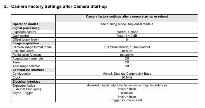
Per the Tap Geometry section of this guide, determine the default tap geometry of your camera. As previously mentioned, you will find this in the camera’s manual. Here is an example with the Baumer HXC20:

As you can see in the manual, the default tap configuration is Dual Tap Camera Link Base. Looking further in the manual, the Dual Tap Camera Link Base configuration is explained:
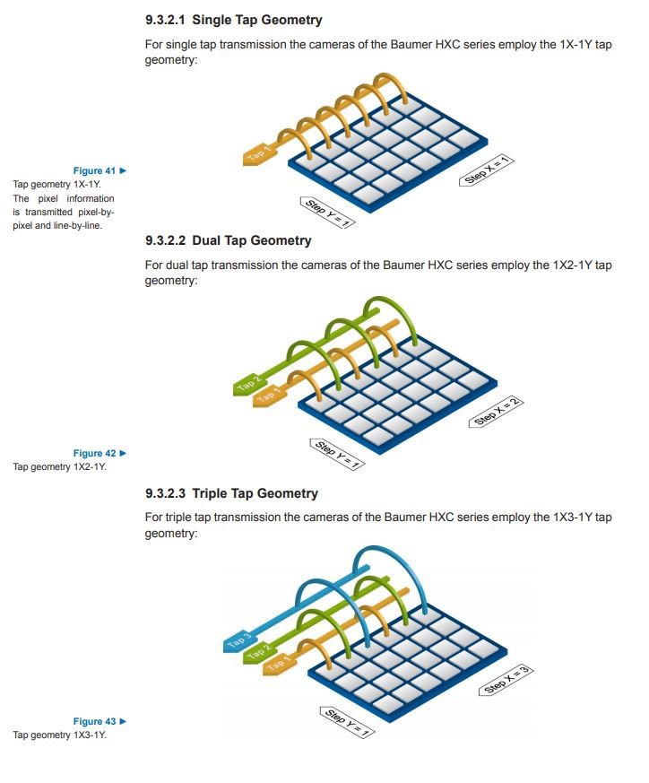
Per the manual, the HXC20’s default configuration is described by section 9.3.2.2 which is 1X2-1Y.
Refer to the following table to know which tap geometry to choose from the Camera File Generator:
Camera File Generator Label | Camera Link Naming Convention |
|---|---|
2 Tap Left/Right | 2X1-1Y1 |
2 Tap Top/Bottom | 1X1-2Y1 |
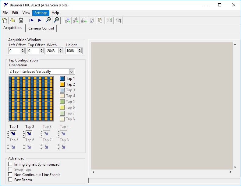
2 Tap Interlaced Vertically | 1X2-1Y1 |
2 Tap Interlaced Horizontally | 1X1-1Y2 |
3 Tap Interlaced Vertically | 1X3-1Y1 |
4 Tap Vertical Sections | 4X1-1Y1 |
4 Tap Horizontal Sections | 1X1-4Y1 |
4 Tap Interlaced Vertically | 1X4-1Y1 |
4 Tap Split Interlaced Vertically | 2X2-1Y1 |
4 Tap Interlaced Horizontally | 1X1-1Y4 |
4 Tap Quadrants | 2X1-2Y1 |
8 Tap Vertical Sections | 8X1-1Y1 |
8 Tap Interlaced Vertically | 1X8-1Y1 |
8 Tap Horizontal Sections | 1X1-8Y1 |
8 Tap Interlaced Horizontally | 1X1-1Y8 |
10 Tap Interlaced Vertically | 1X10⁻¹Y1 |
This table shows the correspondence of the Tap Configuration Orientation used in Camera File Generator and the Camera Link Tap Geometry Naming Convention.
1X2-1Y corresponds to 2 Tap Interlaced Vertically in the Camera File Generator.
Enabling Power Over Camera Link (PoCL)
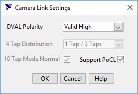
If you are using a frame grabber and camera that supports PoCL, you can enable that feature in the camera file in order to make use of it. Go to Settings > Camera Link Settings and enable “Support PoCL”:
Acquisition in Camera File Generator
Once you have entered all the settings required for a basic acquisition, you can test the result by doing a Grab.
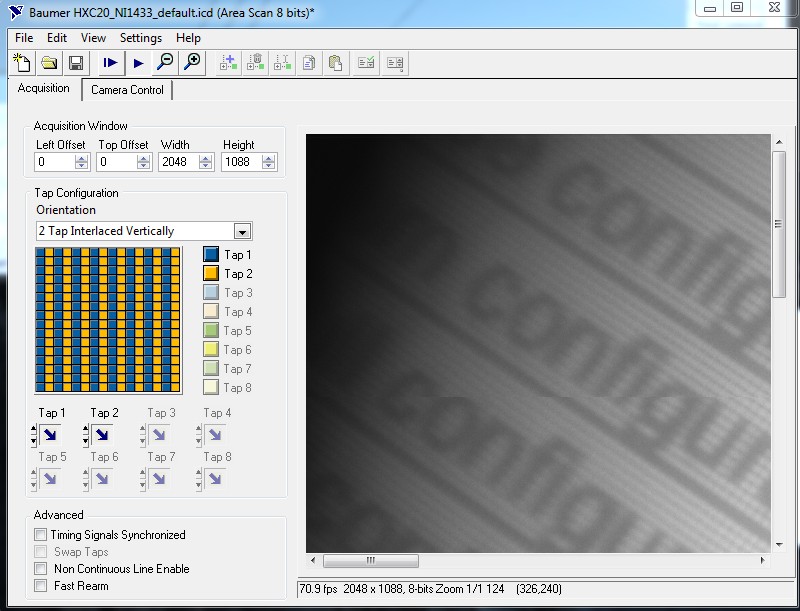
If you are getting an error or a corrupted image, refer to the Camera Link Troubleshooting Guide.
Camera Control in Camera File Generator
Once you have a basic acquisition working, you can now add attributes to your camera file in order to control/change the settings of your camera without using the camera vendor’s software utility.
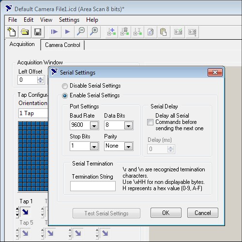
- Setting up Serial Settings
To communicate with your camera, you need to ensure the serial settings of the frame grabber match your cameras. By clicking on Settings > Serial Settings, you can configure: baud rate, data bits, stop bits, parity and termination string. The camera’s serial settings should be in the User Manual.
-
Configuring serial commands
-
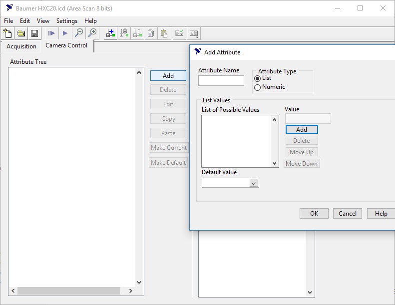
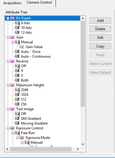
Select the Camera Control Tab to see the Attribute Tree. There, you can add your camera’s attributes and its list of possible values. Refer to the manual of your camera to get the list of attributes and serial commands.
-
Click on Add to create a new attribute. Click on Help to learn more about the different types of attributes and how to use them.
-
c. Once you have created the attributes that match the capabilities of your camera, you can add serial and pulse generation
actions for those attributes.
Refer to Adding Actions section of the Camera File Generator help to learn more about how to configure and test these settings.
Saving Camera File
At this point you can save your .icd file.
-
Place the *.icd file in C:\Users\Public\Public Documents\National Instruments\NI-IMAQ\Data
-
Once the file is placed in the correct directory, launch MAX and find your frame grabber under the Devices and Interfaces list in the Configuration tree. You will see a camera under the frame grabber, right-click and select Camera Selection from the context menu. Select the appropriate camera file from the list.
Note: If you make changes in the Camera File Generator while MAX is opened, hit refresh (f5) to make sure your changes are re-loaded.