Harmonics
- Updated2026-02-01
- 6 minute(s) read
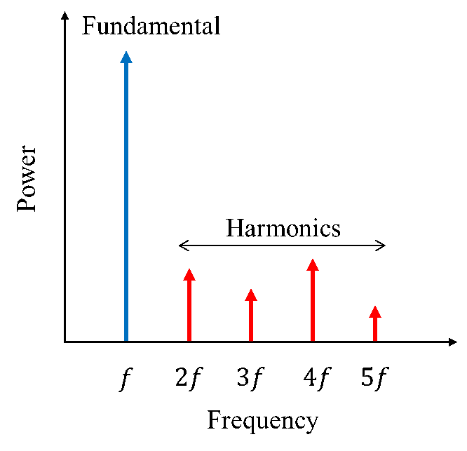
A harmonic of a signal, referred to as the fundamental, is the signal at an integer multiple of the fundamental frequency. If the fundamental frequency is f, the harmonics are signals at frequencies 2f, 3f, 4f, and so on. These harmonics are identified by order. For example, the harmonic at 2f is called the second-order harmonic. Similarly, the harmonic at n×f is called the nth order harmonic.
The following figure shows the configuration of fundamental and harmonics.
Harmonic distortions are inherent to devices and systems that have nonlinear characteristics. The total harmonic distortion (THD(%)) is a measure of these distortions. THD is calculated using the following formula:

Fundamental and Harmonics Configuration
The RF center frequency is considered as the fundamental frequency. The power measured at the fundamental is as seen through an RBW filter for the duration specified by the measurement interval.
A harmonic is defined by the order, the RBW filter bandwidth, and the measurement interval.
The fundamental RBW filter type and RRC alpha settings configured using the fundamental configuration are applicable for all harmonics in both auto and manual harmonic setup.
You can configure harmonics in the following ways:
Auto Harmonic Setup
Auto harmonic setup uses the fundamental configuration to derive the harmonic configuration. You must specify the number of harmonics to be measured. The configured number of harmonics includes the fundamental. The nth harmonic configuration is derived from the fundamental configuration using the following equations. Auto harmonics setup can be enabled by setting Harm Harmonics Auto Setup Enabled property to True.

The RBW filter type and RRC alpha settings for each harmonic are same as those configured for the fundamental.
For a specified RBW filter type, the digital filter response includes the excess bandwidth to realize the shape of the traditional analog RBW filter. Refer to the Spectral Measurements topic for more details on RBW filters.
If the excess span of the resolution bandwidth filter corresponding to the nth harmonic exceeds the device instantaneous bandwidth (DIBW) of the signal analyzer, the measurement coerces nth harmonic 3dB RBW and measurement interval. This coercion is required only when the measurement method is set to Time Domain.
The measurement coerces the nth harmonic 3dB RBW using the following equation:

The measurement coerces the nth harmonic measurement interval using the following equation:

Manual Harmonic Setup
Manual harmonic setup allows you to set the order, RBW filter bandwidth, and the measurement interval for the fundamental and each harmonic by using the per-harmonic configuration. The fundamental RBW and measurement interval configured using fundamental configuration are ignored. Instead, the fundamental is configured using the first element of the per-harmonic configuration, and therefore, must be enabled with order set to 1. The harmonics are configured from second element onwards. When the harmonics are configured using selector strings, the fundamental must be configured using the “harmonic<0>” string. Manual harmonics setup can be enabled by setting the Harm Harmonics Auto Setup Enabled property to False.
Measurement Method
Harmonics measurement supports two measurement methods based on the requirements of measurement speed and dynamic range.
- Time Domain – This method performs zero span measurement using the time-domain signal as seen through RBW filter for the specified measurement interval.
- Dynamic Range – This method improves the dynamic range when
measuring harmonics in presence of the fundamental signal. To achieve this, the
measurement performs acquisition using narrow band IF filters to isolate the
harmonic being measured, followed by IF gain stages for reducing quantization noise
of the digitizer. This method performs harmonic power measurements in the
frequency-domain.
Supported signal analyzers: PXIe-5665, PXIe-5668
Noise Compensation
Noise compensation can be used to further improve the dynamic range by reducing the impact of signal analyzer’s thermal noise contribution to the measurement. When noise compensation is enabled, the measurement is performed in two steps. The first step approximates the noise contribution of the signal analyzer. The acquisitions are averaged to obtain a reliable estimate of the signal analyzer's noise. The second step measures the power at the fundamental and the harmonics followed by subtraction of the signal analyzer's noise measured in the first step.
To optimize the execution speed of the measurement, the noise measured in the first step is cached so that the measurement can use it later, provided, the measurement configurations and state of the signal analyzer remains the same. When the signal analyzer or measurement parameters change, the first step is reinitiated to return valid measurements.
Supported signal analyzers: PXIe-5665, PXIe-5668
Recommended Settings
Signal Generator Considerations
The non-linearity in the signal generator can produce harmonics and limit the dynamic range when measuring harmonics from a DUT. To generate a clean signal, use a band pass or a low pass filter after the signal generator to filter out the harmonics. The following diagram shows a typical hardware setup for harmonics measurement.

Signal Analyzer Considerations
Operate the analyzer at an optimal mixer level to minimize the distortion contributed by the signal analyzer.
Mixer Level (dBm) = Reference Level (dBm) – RF Attenuation (dB)
The following steps help to improve the dynamic range of the measurement:
- The RF input attenuation must be set such that the mixer operates at optimal operating level. Refer to the dynamic range chart of the device to know the optimum mixer level.
- To maximize the dynamic range of the ADC, configure the reference level equal to the peak power of the fundamental signal assuming the test setup is such that the fundamental is not filtered out.
To verify if the signal analyzer is contributing to the distortions, vary the RF input attenuator setting. If the measured distortion amplitude does not change on varying RF attenuation, the distortion is entirely because of the DUT. However, if the distortion amplitude changes, then signal analyzer is also contributing to the distortion.
- The power at the fundamental and the harmonics are measured using the same reference level and is not adjusted on per-harmonic basis.
- Consider using RBW for all harmonics equal to that of the fundamental signal when the fundamental signal is a sinusoid. This can be achieved by using manual harmonic setup.
- Recommended signal analyzers: PXIe-5665, PXIe-5668
High Pass Filters
The fundamental signal can be filtered out, using a high pass filter (HPF) before the signal analyzer, to further improve the dynamic range by setting very low reference level. The following figure shows test setup with an external high pass filter before signal analyzer.
