IMAQ FPGA MulDiv VI
- Updated2023-02-21
- 40 minute(s) read
Requires: NI Vision Development Module FPGA
Computes a ratio between two images. Each pixel in Pixel Bus In A is multiplied by the integer value specified in the input Constant before being divided by the equivalent pixel found in Pixel Bus In B. To avoid losing information, a temporary variable giving higher definition is used to perform the operation. If the background is lighter than the image, this function can correct the background. In a background correction image, Pixel Bus In A is the acquired image, and Pixel Bus In B is the light background.
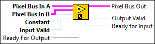
IMAQ FPGA MulDiv U8 x1
Computes a ratio between two images. Each pixel in Pixel Bus In A is multiplied by the integer value specified in the input Constant before being divided by the equivalent pixel found in Pixel Bus In B. To avoid losing information, a temporary variable giving higher definition is used to perform the operation. If the background is lighter than the image, this function can correct the background. In a background correction image, Pixel Bus In A is the acquired image, and Pixel Bus In B is the light background.
Supported Image Types

 |
Pixel Bus In A when Input Valid is TRUE, contains one of the following: valid pixel data, an end of line signal, or an end of image signal.
|
||||||||||
|
Pixel Bus In B when Input Valid is TRUE, contains one of the following: valid pixel data, an end of line signal, or an end of image signal.
|
||||||||||
 |
Constant is the value multiplied by each pixel in Pixel Bus In A before each pixel in Pixel Bus In B is divided by the equivalent pixel in Pixel Bus In B. |
||||||||||
 |
Input Valid specifies whether the next data point has arrived for processing. Wire the Output Valid output of an upstream node to this input to transfer data from the upstream node to this node. |
||||||||||
|
Ready For Output specifies whether downstream nodes are ready for this node to return a new value. The default is TRUE. Use a Feedback Node to wire the Ready for Input output of a downstream node to this input of the current node.
|
||||||||||
 |
Pixel Bus Out when Input Valid is TRUE, contains one of the following: valid pixel data, an end of line signal, or an end of image signal.
|
||||||||||
 |
Output Valid returns TRUE if this node has computed a result that downstream nodes can use. Wire this output to the Input Valid input of a downstream node to transfer data from the node to the downstream node. |
||||||||||
|
Ready for Input returns TRUE if this node is ready to accept new input data. Use a Feedback Node to wire this output to the Ready for Output input of an upstream node.
|


IMAQ FPGA MulDiv U8 x1 Details
 |
Note Resource estimates are based on a 40 MHz clock. |
Virtex-5
Estimated Device Utilization
- Slice Registers: 428
- Slice LUTs: 508
- DSP48s: 1
- Block RAMs: 0
Estimated Performance
- Minimum Latency: 9
- Initiation Interval: 1
Spartan-6
Estimated Device Utilization
- Slice Registers: 440
- Slice LUTs: 498
- DSP48s: 1
- Block RAMs: 0
Estimated Performance
- Minimum Latency: 9
- Initiation Interval: 1
Zynq
Estimated Device Utilization
- Slice Registers: 427
- Slice LUTs: 412
- DSP48s: 1
- Block RAMs: 0
Estimated Performance
- Minimum Latency: 7
- Initiation Interval: 1
Kintex-7
Estimated Device Utilization
- Slice Registers: 429
- Slice LUTs: 430
- DSP48s: 1
- Block RAMs: 0
Estimated Performance
- Minimum Latency: 7
- Initiation Interval: 1
IMAQ FPGA MulDiv U8 x8
Computes a ratio between two images. Each pixel in Pixel Bus In A is multiplied by the integer value specified in the input Constant before being divided by the equivalent pixel found in Pixel Bus In B. To avoid losing information, a temporary variable giving higher definition is used to perform the operation. If the background is lighter than the image, this function can correct the background. In a background correction image, Pixel Bus In A is the acquired image, and Pixel Bus In B is the light background.
Supported Image Types

|
Pixel Bus In A when Input Valid is TRUE, contains one of the following: valid pixel data, an end of line signal, or an end of image signal.
|
||||||||||
|
Pixel Bus In B when Input Valid is TRUE, contains one of the following: valid pixel data, an end of line signal, or an end of image signal.
|
||||||||||
|
Constant is the value multiplied by each pixel in Pixel Bus In A before each pixel in Pixel Bus In B is divided by the equivalent pixel in Pixel Bus In B. |
||||||||||
|
Input Valid specifies whether the next data point has arrived for processing. Wire the Output Valid output of an upstream node to this input to transfer data from the upstream node to this node. |
||||||||||
|
Ready For Output specifies whether downstream nodes are ready for this node to return a new value. The default is TRUE. Use a Feedback Node to wire the Ready for Input output of a downstream node to this input of the current node.
|
||||||||||
|
Pixel Bus Out when Input Valid is TRUE, contains one of the following: valid pixel data, an end of line signal, or an end of image signal.
|
||||||||||
|
Output Valid returns TRUE if this node has computed a result that downstream nodes can use. Wire this output to the Input Valid input of a downstream node to transfer data from the node to the downstream node. |
||||||||||
|
Ready for Input returns TRUE if this node is ready to accept new input data. Use a Feedback Node to wire this output to the Ready for Output input of an upstream node.
|
IMAQ FPGA MulDiv U8 x8 Details
|
Note Resource estimates are based on a 40 MHz clock. |
Kintex-7
Estimated Device Utilization
- Slice Registers: 2427
- Slice LUTs: 2586
- DSP48s: 8
- Block RAMs: 0
Estimated Performance
- Minimum Latency: 1
- Initiation Interval: 1
IMAQ FPGA MulDiv U16 x1
Computes a ratio between two images. Each pixel in Pixel Bus In A is multiplied by the integer value specified in the input Constant before being divided by the equivalent pixel found in Pixel Bus In B. To avoid losing information, a temporary variable giving higher definition is used to perform the operation. If the background is lighter than the image, this function can correct the background. In a background correction image, Pixel Bus In A is the acquired image, and Pixel Bus In B is the light background.
Supported Image Types


|
Pixel Bus In A when Input Valid is TRUE, contains one of the following: valid pixel data, an end of line signal, or an end of image signal.
|
||||||||||
|
Pixel Bus In B when Input Valid is TRUE, contains one of the following: valid pixel data, an end of line signal, or an end of image signal.
|
||||||||||
|
Constant is the value multiplied by each pixel in Pixel Bus In A before each pixel in Pixel Bus In B is divided by the equivalent pixel in Pixel Bus In B. |
||||||||||
|
Input Valid specifies whether the next data point has arrived for processing. Wire the Output Valid output of an upstream node to this input to transfer data from the upstream node to this node. |
||||||||||
|
Ready For Output specifies whether downstream nodes are ready for this node to return a new value. The default is TRUE. Use a Feedback Node to wire the Ready for Input output of a downstream node to this input of the current node.
|
||||||||||
|
Pixel Bus Out when Input Valid is TRUE, contains one of the following: valid pixel data, an end of line signal, or an end of image signal.
|
||||||||||
|
Output Valid returns TRUE if this node has computed a result that downstream nodes can use. Wire this output to the Input Valid input of a downstream node to transfer data from the node to the downstream node. |
||||||||||
|
Ready for Input returns TRUE if this node is ready to accept new input data. Use a Feedback Node to wire this output to the Ready for Output input of an upstream node.
|


IMAQ FPGA MulDiv U16 x1 Details
|
Note Resource estimates are based on a 40 MHz clock. |
Virtex-5
Estimated Device Utilization
- Slice Registers: 916
- Slice LUTs: 1216
- DSP48s: 1
- Block RAMs: 0
Estimated Performance
- Minimum Latency: 16
- Initiation Interval: 1
Spartan-6
Estimated Device Utilization
- Slice Registers: 932
- Slice LUTs: 1259
- DSP48s: 2
- Block RAMs: 0
Estimated Performance
- Minimum Latency: 16
- Initiation Interval: 1
Zynq
Estimated Device Utilization
- Slice Registers: 980
- Slice LUTs: 1026
- DSP48s: 1
- Block RAMs: 0
Estimated Performance
- Minimum Latency: 12
- Initiation Interval: 1
Kintex-7
Estimated Device Utilization
- Slice Registers: 953
- Slice LUTs: 981
- DSP48s: 1
- Block RAMs: 0
Estimated Performance
- Minimum Latency: 12
- Initiation Interval: 1
IMAQ FPGA MulDiv U16 x8
Computes a ratio between two images. Each pixel in Pixel Bus In A is multiplied by the integer value specified in the input Constant before being divided by the equivalent pixel found in Pixel Bus In B. To avoid losing information, a temporary variable giving higher definition is used to perform the operation. If the background is lighter than the image, this function can correct the background. In a background correction image, Pixel Bus In A is the acquired image, and Pixel Bus In B is the light background.
Supported Image Types

|
Pixel Bus In A when Input Valid is TRUE, contains one of the following: valid pixel data, an end of line signal, or an end of image signal.
|
||||||||||
|
Pixel Bus In B when Input Valid is TRUE, contains one of the following: valid pixel data, an end of line signal, or an end of image signal.
|
||||||||||
|
Constant is the value multiplied by each pixel in Pixel Bus In A before each pixel in Pixel Bus In B is divided by the equivalent pixel in Pixel Bus In B. |
||||||||||
|
Input Valid specifies whether the next data point has arrived for processing. Wire the Output Valid output of an upstream node to this input to transfer data from the upstream node to this node. |
||||||||||
|
Ready For Output specifies whether downstream nodes are ready for this node to return a new value. The default is TRUE. Use a Feedback Node to wire the Ready for Input output of a downstream node to this input of the current node.
|
||||||||||
|
Pixel Bus Out when Input Valid is TRUE, contains one of the following: valid pixel data, an end of line signal, or an end of image signal.
|
||||||||||
|
Output Valid returns TRUE if this node has computed a result that downstream nodes can use. Wire this output to the Input Valid input of a downstream node to transfer data from the node to the downstream node. |
||||||||||
|
Ready for Input returns TRUE if this node is ready to accept new input data. Use a Feedback Node to wire this output to the Ready for Output input of an upstream node.
|
IMAQ FPGA MulDiv U16 x8 Details
|
Note Resource estimates are based on a 40 MHz clock. |
Kintex-7
Estimated Device Utilization
- Slice Registers: 6458
- Slice LUTs: 6741
- DSP48s: 8
- Block RAMs: 0
Estimated Performance
- Minimum Latency: 1
- Initiation Interval: 1
IMAQ FPGA MulDiv rgb32 x1
Computes a ratio between two images. Each pixel in Pixel Bus In A is multiplied by the integer value specified in the input Constant before being divided by the equivalent pixel found in Pixel Bus In B. To avoid losing information, a temporary variable giving higher definition is used to perform the operation. If the background is lighter than the image, this function can correct the background. In a background correction image, Pixel Bus In A is the acquired image, and Pixel Bus In B is the light background.
Supported Image Types


|
Pixel Bus In A when Input Valid is TRUE, contains one of the following: valid pixel data, an end of line signal, or an end of image signal.
|
||||||||||||||||||
|
Pixel Bus In B when Input Valid is TRUE, contains one of the following: valid pixel data, an end of line signal, or an end of image signal.
|
||||||||||||||||||
|
Constant is the value multiplied by each pixel in Pixel Bus In A before each pixel in Pixel Bus In B is divided by the equivalent pixel in Pixel Bus In B. |
||||||||||||||||||
|
Input Valid specifies whether the next data point has arrived for processing. Wire the Output Valid output of an upstream node to this input to transfer data from the upstream node to this node. |
||||||||||||||||||
|
Ready For Output specifies whether downstream nodes are ready for this node to return a new value. The default is TRUE. Use a Feedback Node to wire the Ready for Input output of a downstream node to this input of the current node.
|
||||||||||||||||||
|
Pixel Bus Out when Input Valid is TRUE, contains one of the following: valid pixel data, an end of line signal, or an end of image signal.
|
||||||||||||||||||
|
Output Valid returns TRUE if this node has computed a result that downstream nodes can use. Wire this output to the Input Valid input of a downstream node to transfer data from the node to the downstream node. |
||||||||||||||||||
|
Ready for Input returns TRUE if this node is ready to accept new input data. Use a Feedback Node to wire this output to the Ready for Output input of an upstream node.
|


IMAQ FPGA MulDiv rgb32 x1 Details
|
Note Resource estimates are based on a 40 MHz clock. |
Virtex-5
Estimated Device Utilization
- Slice Registers: 1061
- Slice LUTs: 1314
- DSP48s: 3
- Block RAMs: 0
Estimated Performance
- Minimum Latency: 9
- Initiation Interval: 1
Spartan-6
Estimated Device Utilization
- Slice Registers: 1093
- Slice LUTs: 1437
- DSP48s: 3
- Block RAMs: 0
Estimated Performance
- Minimum Latency: 9
- Initiation Interval: 1
Zynq
Estimated Device Utilization
- Slice Registers: 1066
- Slice LUTs: 1138
- DSP48s: 3
- Block RAMs: 0
Estimated Performance
- Minimum Latency: 7
- Initiation Interval: 1
Kintex-7
Estimated Device Utilization
- Slice Registers: 1039
- Slice LUTs: 1040
- DSP48s: 3
- Block RAMs: 0
Estimated Performance
- Minimum Latency: 7
- Initiation Interval: 1
IMAQ FPGA MulDiv rgb32 x8
Computes a ratio between two images. Each pixel in Pixel Bus In A is multiplied by the integer value specified in the input Constant before being divided by the equivalent pixel found in Pixel Bus In B. To avoid losing information, a temporary variable giving higher definition is used to perform the operation. If the background is lighter than the image, this function can correct the background. In a background correction image, Pixel Bus In A is the acquired image, and Pixel Bus In B is the light background.
Supported Image Types

|
Pixel Bus In A when Input Valid is TRUE, contains one of the following: valid pixel data, an end of line signal, or an end of image signal.
|
||||||||||||||||||
|
Pixel Bus In B when Input Valid is TRUE, contains one of the following: valid pixel data, an end of line signal, or an end of image signal.
|
||||||||||||||||||
|
Constant is the value multiplied by each pixel in Pixel Bus In A before each pixel in Pixel Bus In B is divided by the equivalent pixel in Pixel Bus In B. |
||||||||||||||||||
|
Input Valid specifies whether the next data point has arrived for processing. Wire the Output Valid output of an upstream node to this input to transfer data from the upstream node to this node. |
||||||||||||||||||
|
Ready For Output specifies whether downstream nodes are ready for this node to return a new value. The default is TRUE. Use a Feedback Node to wire the Ready for Input output of a downstream node to this input of the current node.
|
||||||||||||||||||
|
Pixel Bus Out when Input Valid is TRUE, contains one of the following: valid pixel data, an end of line signal, or an end of image signal.
|
||||||||||||||||||
|
Output Valid returns TRUE if this node has computed a result that downstream nodes can use. Wire this output to the Input Valid input of a downstream node to transfer data from the node to the downstream node. |
||||||||||||||||||
|
Ready for Input returns TRUE if this node is ready to accept new input data. Use a Feedback Node to wire this output to the Ready for Output input of an upstream node.
|
IMAQ FPGA MulDiv rgb32 x8 Details
|
Note Resource estimates are based on a 40 MHz clock. |
Kintex-7
Estimated Device Utilization
- Slice Registers: 7595
- Slice LUTs: 7941
- DSP48s: 24
- Block RAMs: 0
Estimated Performance
- Minimum Latency: 1
- Initiation Interval: 1
IMAQ FPGA MulDiv hsl32 x1
Computes a ratio between two images. Each pixel in Pixel Bus In A is multiplied by the integer value specified in the input Constant before being divided by the equivalent pixel found in Pixel Bus In B. To avoid losing information, a temporary variable giving higher definition is used to perform the operation. If the background is lighter than the image, this function can correct the background. In a background correction image, Pixel Bus In A is the acquired image, and Pixel Bus In B is the light background.
Supported Image Types


|
Pixel Bus In A when Input Valid is TRUE, contains one of the following: valid pixel data, an end of line signal, or an end of image signal.
|
||||||||||||||||||
|
Pixel Bus In B when Input Valid is TRUE, contains one of the following: valid pixel data, an end of line signal, or an end of image signal.
|
||||||||||||||||||
|
Constant is the value multiplied by each pixel in Pixel Bus In A before each pixel in Pixel Bus In B is divided by the equivalent pixel in Pixel Bus In B. |
||||||||||||||||||
|
Input Valid specifies whether the next data point has arrived for processing. Wire the Output Valid output of an upstream node to this input to transfer data from the upstream node to this node. |
||||||||||||||||||
|
Ready For Output specifies whether downstream nodes are ready for this node to return a new value. The default is TRUE. Use a Feedback Node to wire the Ready for Input output of a downstream node to this input of the current node.
|
||||||||||||||||||
|
Pixel Bus Out when Input Valid is TRUE, contains one of the following: valid pixel data, an end of line signal, or an end of image signal.
|
||||||||||||||||||
|
Output Valid returns TRUE if this node has computed a result that downstream nodes can use. Wire this output to the Input Valid input of a downstream node to transfer data from the node to the downstream node. |
||||||||||||||||||
|
Ready for Input returns TRUE if this node is ready to accept new input data. Use a Feedback Node to wire this output to the Ready for Output input of an upstream node.
|
IMAQ FPGA MulDiv hsl32 x1 Details
|
Note Resource estimates are based on a 40 MHz clock. |
Virtex-5
Estimated Device Utilization
- Slice Registers: 1061
- Slice LUTs: 1315
- DSP48s: 3
- Block RAMs: 0
Estimated Performance
- Minimum Latency: 9
- Initiation Interval: 1
Spartan-6
Estimated Device Utilization
- Slice Registers: 1093
- Slice LUTs: 1437
- DSP48s: 3
- Block RAMs: 0
Estimated Performance
- Minimum Latency: 9
- Initiation Interval: 1
Zynq
Estimated Device Utilization
- Slice Registers: 1066
- Slice LUTs: 1139
- DSP48s: 3
- Block RAMs: 0
Estimated Performance
- Minimum Latency: 7
- Initiation Interval: 1
Kintex-7
Estimated Device Utilization
- Slice Registers: 1039
- Slice LUTs: 1041
- DSP48s: 3
- Block RAMs: 0
Estimated Performance
- Minimum Latency: 7
- Initiation Interval: 1
IMAQ FPGA MulDiv hsl32 x8
Computes a ratio between two images. Each pixel in Pixel Bus In A is multiplied by the integer value specified in the input Constant before being divided by the equivalent pixel found in Pixel Bus In B. To avoid losing information, a temporary variable giving higher definition is used to perform the operation. If the background is lighter than the image, this function can correct the background. In a background correction image, Pixel Bus In A is the acquired image, and Pixel Bus In B is the light background.
Supported Image Types

|
Pixel Bus In A when Input Valid is TRUE, contains one of the following: valid pixel data, an end of line signal, or an end of image signal.
|
||||||||||||||||||
|
Pixel Bus In B when Input Valid is TRUE, contains one of the following: valid pixel data, an end of line signal, or an end of image signal.
|
||||||||||||||||||
|
Constant is the value multiplied by each pixel in Pixel Bus In A before each pixel in Pixel Bus In B is divided by the equivalent pixel in Pixel Bus In B. |
||||||||||||||||||
|
Input Valid specifies whether the next data point has arrived for processing. Wire the Output Valid output of an upstream node to this input to transfer data from the upstream node to this node. |
||||||||||||||||||
|
Ready For Output specifies whether downstream nodes are ready for this node to return a new value. The default is TRUE. Use a Feedback Node to wire the Ready for Input output of a downstream node to this input of the current node.
|
||||||||||||||||||
|
Pixel Bus Out when Input Valid is TRUE, contains one of the following: valid pixel data, an end of line signal, or an end of image signal.
|
||||||||||||||||||
|
Output Valid returns TRUE if this node has computed a result that downstream nodes can use. Wire this output to the Input Valid input of a downstream node to transfer data from the node to the downstream node. |
||||||||||||||||||
|
Ready for Input returns TRUE if this node is ready to accept new input data. Use a Feedback Node to wire this output to the Ready for Output input of an upstream node.
|
IMAQ FPGA MulDiv hsl32 x8 Details
|
Note Resource estimates are based on a 40 MHz clock. |
Kintex-7
Estimated Device Utilization
- Slice Registers: 7595
- Slice LUTs: 7943
- DSP48s: 24
- Block RAMs: 0
Estimated Performance
- Minimum Latency: 1
- Initiation Interval: 1