Using the Stereo Vision Example
- Updated2023-02-21
- 5 minute(s) read
This topic explains how to configure and use the stereo vision example included with NI Vision Development Module. The stereo vision example is installed to the following location: <LabVIEW>\examples\Vision\Stereo Vision\Compute Depth Image\Compute Depth Image.vi, where <LabVIEW> is the location to which you installed LabVIEW.
Configuring the Stereo Vision Example
Before you can use the stereo vision example, you must configure the example to use your cameras.
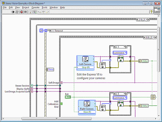
- With the example open, press <CTRL+E> to open the block diagram.
- Locate the NI Vision Acquisition Express VIs:
- Click the selector label of the outermost stacked sequence structure and select frame 2.
- Within the stacked sequence structure, click the selector label of the event structure and select the Timeout event case.
- Within the Timeout event case, click the selector label of the stacked sequence structure and select frame 0.
- Double click the Left Camera express VI to select and configure the left camera.
- Double click the Right Camera express VI to select and configure the right camera.
- After configuring a left and right camera, press <CTRL+E> to return to the example front panel.
- Run the stereo vision example.
Preparing to Use the Stereo Vision Example
The stereo vision example requires you to use a calibration grid to calibrate the cameras. Before calibrating the cameras, verify the following:- The entire calibration grid is within the field of view of both cameras simultaneously.
- You can reposition the calibration grid while viewing the stereo vision example.
During calibration, the example acquires images automatically based on a timer. To adjust the timer, use the Image Acquisition Time Lapse control on the Stereo System Calibration tab.
Calibrating the Stereo Vision System
Calibration requires multiple images of a calibration grid. For the first frame, the entire calibration grid must be within the field of view of both cameras. The entire calibration grid is not required for subsequent frames. For best results, change the angle of the calibration grid between acquisitions according to the illustration displayed at the bottom left of the user interface.
Between each acquisition, reposition the calibration grid so that grid coverage in the combined acquisitions accounts for most of the field of view for both cameras. You cannot complete calibration until you achieve sufficient coverage.
Complete the following steps to calibrate the stereo vision system:
- Select the Stereo System Calibration tab.
- Click Calibrate Stereo System. The Select Grid Parameters dialog box appears.

- Use the dX, dY, and Unit controls to specify the distance between points in your calibration grid.
- Use the X and Y controls to specify the number of points in each row and column of your calibration grid.
- Click OK to close the Select Grid Parameters dialog box.
- Position the calibration grid so that the entire calibration grid is visible to both cameras.


Tip The example displays a red indicator until enough calibration points are visible for each acquisition. For the first acquisition, the example requires all calibration points to be visible to both cameras. - After the initial acquisition, follow the prompts to position the calibration grid at different angles and cover the complete field of view. The following image illustrates a final acquisition with nearly complete grid coverage:

Tip Select Grid Coverage from the Show list and use the green indicators to determine areas that need additional grid coverage. - When the example has sufficient calibration point data, you are prompted to verify the top left point in the calibration grid for each camera.

If the correct point is not selected, select the top left point. Click OK to continue.
The example calculates stereo calibration data and displays rectified images for each camera.
Computing Disparity or Depth Information
NI Vision offers two algorithms for computing stereo correspondence: a block-matching algorithm and a semi-global block-matching algorithm. The block-matching algorithm offers efficient performance while the semi-global block-matching algorithm provides more detail and works in regions with little or no apparent texture. The parameters for each algorithm are displayed on separate tabs in the example.
Both algorithm tabs include a Display list. Use the Display list to specify the output image to display.
- Disparity Image—Indicates the disparity between left and right rectified images. Disparity information indicates the relative depth of an object. Brighter pixels indicate points that are closer to the camera and darker pixels indicate points that are farther away from the camera.
- Depth Image—Provides comprehensive real-world depth information about the scene. Depth information can optionally be rendered to a real-world coordinate system. Click within the depth image to view the 3D coordinate information for the point at the cursor position.
- Error Map—Indicates the inherent error in measurement for each pixel in the depth image.
- Score Image—Indicates the disparity confidence score each pixel in the disparity image.
Use the score image to evaluate the disparity image. Use the error map to evaluate the depth image.
Refer to the Stereo Vision FAQs for more information about setting parameter values for this example.