SI Model Prediction VI
- Updated2023-03-14
- 10 minute(s) read
SI Model Prediction VI
Owning Palette: Model Validation VIs
Requires: Advanced Signal Processing Toolkit or Control Design and Simulation Module
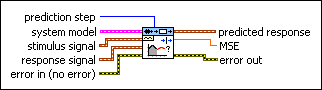
Performs k-step-ahead model prediction on a system model. Wire data to the stimulus signal and response signal inputs to determine the polymorphic instance to use or manually select the instance.
 | Note This VI does not support the transfer function or zero-pole-gain models. For AR models, this VI ignores stimulus signal. |
SI Model Prediction (SISO Waveform)
 |
prediction step specifies the prediction interval. The step-ahead prediction response is estimated by the known stimulus and response data up to the time you estimate the response. If prediction step is less than 0, this VI performs the model simulation without containing a disturbance. You cannot set prediction step to 0. | ||
 |
system model contains information about the model structure, nominal or estimated parameters, identification result, and so on. Use the Model Management VIs to retrieve the information system model contains.
|
||
 |
stimulus signal specifies the input waveform of the stimulus signal. | ||
|
response signal specifies the input waveform of the response signal. | ||
 |
error in describes error conditions that occur before this node runs. This input provides standard error in functionality. | ||
 |
predicted response returns the predicted response waveform of the system. | ||
 |
MSE returns the mean square error (MSE) between response signal and predicted response. | ||
 |
error out contains error information. This output provides standard error out functionality. |
SI Model Prediction (SISO Array)

|
prediction step specifies the prediction interval. The step-ahead prediction response is estimated by the known stimulus and response data up to the time you estimate the response. If prediction step is less than 0, this VI performs the model simulation without containing a disturbance. You cannot set prediction step to 0. | ||
|
system model contains information about the model structure, nominal or estimated parameters, identification result, and so on. Use the Model Management VIs to retrieve the information system model contains.
|
||
 |
stimulus signal specifies an array that represents the stimulus signal. | ||
|
response signal specifies an array that represents the response signal. | ||
|
error in describes error conditions that occur before this node runs. This input provides standard error in functionality. | ||
 |
sampling rate (Hz) specifies the sampling rate of the input signals. sampling rate must equal the sampling rate used to estimate the system model. | ||
 |
predicted response returns the predicted response output of the system. | ||
|
MSE returns the mean square error (MSE) between response signal and predicted response. | ||
|
error out contains error information. This output provides standard error out functionality. |
SI Model Prediction (MISO Waveform)

|
prediction step specifies the prediction interval. The step-ahead prediction response is estimated by the known stimulus and response data up to the time you estimate the response. If prediction step is less than 0, this VI performs the model simulation without containing a disturbance. You cannot set prediction step to 0. | ||
|
system model contains information about the model structure, nominal or estimated parameters, identification result, and so on. Use the Model Management VIs to retrieve the information system model contains.
|
||
 |
stimulus signals specifies the input waveform array of the stimulus signals. Each element of the array is the waveform of one stimulus signal. | ||
|
response signal specifies the input waveform of the response signal. | ||
|
error in describes error conditions that occur before this node runs. This input provides standard error in functionality. | ||
|
predicted response returns the predicted response waveform of the system. | ||
|
MSE returns the mean square error (MSE) between response signal and predicted response. | ||
|
error out contains error information. This output provides standard error out functionality. |
SI Model Prediction (MISO Array)

|
prediction step specifies the prediction interval. The step-ahead prediction response is estimated by the known stimulus and response data up to the time you estimate the response. If prediction step is less than 0, this VI performs the model simulation without containing a disturbance. You cannot set prediction step to 0. | ||
|
system model contains information about the model structure, nominal or estimated parameters, identification result, and so on. Use the Model Management VIs to retrieve the information system model contains.
|
||
 |
stimulus signals specifies an array that represents the stimulus signals. Each row in the array is one stimulus signal. | ||
|
response signal specifies an array that represents the response signal. | ||
|
error in describes error conditions that occur before this node runs. This input provides standard error in functionality. | ||
|
sampling rate (Hz) specifies the sampling rate of the input signals. sampling rate must equal the sampling rate used to estimate the system model. | ||
|
predicted response returns the predicted response output of the system. | ||
|
MSE returns the mean square error (MSE) between response signal and predicted response. | ||
|
error out contains error information. This output provides standard error out functionality. |
SI Model Prediction (MIMO Waveform)

|
prediction step specifies the prediction interval. The step-ahead prediction response is estimated by the known stimulus and response data up to the time you estimate the response. If prediction step is less than 0, this VI performs the model simulation without containing a disturbance. You cannot set prediction step to 0. | ||
|
system model contains information about the model structure, nominal or estimated parameters, identification result, and so on. Use the Model Management VIs to retrieve the information system model contains.
|
||
|
stimulus signals specifies the input waveform array of the stimulus signals. Each element of the array is the waveform of one stimulus signal. | ||
|
response signals specifies the input waveform array of the response signals. Each element of the array is the waveform of one response signal. | ||
|
error in describes error conditions that occur before this node runs. This input provides standard error in functionality. | ||
 |
predicted responses returns the predicted response waveform array of the system. Each element of the waveform array is the waveform of one response signal. | ||
|
MSEs returns the mean square errors (MSEs) between response signals and predicted responses. Each element of the array is the mean square error of one output. | ||
|
error out contains error information. This output provides standard error out functionality. |
SI Model Prediction (MIMO Array)

|
prediction step specifies the prediction interval. The step-ahead prediction response is estimated by the known stimulus and response data up to the time you estimate the response. If prediction step is less than 0, this VI performs the model simulation without containing a disturbance. You cannot set prediction step to 0. | ||
|
system model contains information about the model structure, nominal or estimated parameters, identification result, and so on. Use the Model Management VIs to retrieve the information system model contains.
|
||
|
stimulus signals specifies an array that represents the stimulus signals. Each row in the array is one stimulus signal. | ||
|
response signals specifies an array that represents the response signals. Each row in the array is one response signal. | ||
|
error in describes error conditions that occur before this node runs. This input provides standard error in functionality. | ||
|
sampling rate (Hz) specifies the sampling rate of the input signals. sampling rate must equal the sampling rate used to estimate the system model. | ||
 |
predicted responses returns the predicted response array of the system. Each row in the array is the output of one response signal. | ||
|
MSEs returns the mean square errors (MSEs) between response signals and predicted responses. Each element of the array is the mean square error of one output. | ||
|
error out contains error information. This output provides standard error out functionality. |
Examples
Refer to the following VIs for examples of using the SI Model Prediction VI:
- Model Prediction VI: labview\examples\System Identification\Getting Started\General.llb
- Flexible Arm VI: labview\examples\System Identification\Industry Applications\Mechanical Systems.llb
- Four-Stage Evaporator VI: labview\examples\System Identification\Industry Applications\Process Industry Systems.llb