Configuring Simulation Functions from the Block Diagram (Control Design and Simulation Module)
- Updated2023-03-14
- 4 minute(s) read
You can wire values to input terminals on Simulation functions and subsystems to configure their model parameters. For functions in subsystems, you can build the connector pane of the subsystem and wire values through the connector pane. To display input terminals on a function or subsystem, use the configuration dialog box for that node to select that option.
In applications with nested subsystems and multiple functions you want to configure, wiring values into and out of subsystems can require a lot of wiring. Instead, use the approaches in the following sections of this topic to access model parameters at any level in the hierarchy of a simulation diagram without performing those tasks.
Initializing Model Parameters
In the following block diagram, the Access Model Hierarchy function initializes the amplitude parameter of two Sine Signal functions in different subsystems before the simulation runs. You can set any parameter that is unwired in the simulation diagram where the parameter resides.
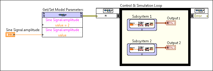
The previous block diagram shows the first amplitude parameter set to 2 from within the configuration dialog box for the Access Model Hierarchy function. The value of the second amplitude parameter comes from an input terminal. You also can identify which parameter you want to configure in either the configuration dialog box or through an input terminal. Refer to the section on accessing parameters in other VIs for an example of identifying a parameter through an input terminal.
Refer to the SimEx Initializing Model Parameters VI in the labview\examples\Control and Simulation\Simulation\Get-Set Model Parameters directory for an example of initializing model parameters.
Tutorial: Configuring Simulation Functions and Accessing Signals in a Simulation Hierarchy
Updating Model Parameters at Run Time
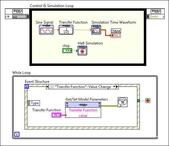
You also can use the Access Model Hierarchy function to change model parameters of functions and subsystems at run time. The following block diagram allows users to update the equation that the Transfer Function function implements while the VI runs. Users change the coefficients in the Transfer Function control and the Access Model Hierarchy function updates that parameter.
Refer to the SimEx Setting Model Parameters at Runtime VI in the labview\examples\Control and Simulation\Simulation\Get-Set Model Parameters directory for an example of setting model parameters at run time.
Accessing Model Parameters in Other VIs
You can use the Access Model Hierarchy function to access model parameters in other VIs, including VIs that run on RT targets. The configuration dialog box for the function allows you to manually identify parameters you want to access in a different VI on the local computer. You also can write code similar to the following block diagram to identify the simulation VI and parameters programmatically.
 |
Note This function must execute while the VI or subsystem that contains the model parameters is running or reserved for execution. Otherwise, LabVIEW ignores the configuration when the function runs and returns warning –2387. |

As shown in the previous block diagram, parameter paths require a specific format.
The following block diagram shows an example of opening a reference to an RT VI that contains a simulation diagram and writing a value to a model parameter.

|
Note You must use the VI Server page of the RT Target Properties dialog box to enable VI Server on a target before you can use this function to access VIs that run on the target. |
Alternative Methods for Configuring Parameters
You also can manually configure Simulation functions at edit time.