Create Mesh with Attributes
- Updated2025-07-30
- 5 minute(s) read
Creates a mesh with customizable color and draw options.
Inputs/Outputs
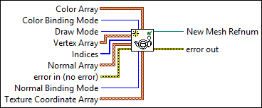
 Color Array
—
Color Array
—
Color Array specifies the RGBA color values for the colors that Color Binding Mode applies to the 3D object. Color Binding Mode references only the first index in the array if you set the mode to Overall whereas it references the respective number of indices if you set the mode to Per Primitive or Per Vertex.
 Color Binding Mode
—
Color Binding Mode
—
Color Binding Mode specifies the mode to use to bind color to the mesh. The mode determines how LabVIEW assigns the color you specify in Color Array. Note The Per Primitive and Overall modes differ in behavior only when Draw Mode is Points, Lines, Triangles, or Quads.
Draw Mode
—
Draw Mode specifies the mode LabVIEW uses to draw the mesh. The mode determines how LabVIEW interprets the data you wire to Vertex Array.
Vertex Array
—
Vertex Array sets the x, y, and z coordinate values in 3D space that LabVIEW uses to draw the mesh. The settings you specify in Color Array, Draw Mode, and Indices determine how LabVIEW interprets the vertices.
 Indices
—
Indices
—
Indices determines the order in which LabVIEW processes the data in the Color Array and Vertex Array of the mesh. For example, if Indices is [3, 2, 4, 1], then V0 appears at index 3 in the Vertex Array, the color of V0 appears at index 3 in the Color Array, and so on. Note If you set Color Binding Mode to Per Primitive, the color refers to the entire face formed by V0, V1…VN (where Draw Mode determines N) rather than only the index you specify.
Normal Array
—
Normal Array sets the x, y, and z values that define the array of normals that Normal Binding Mode applies to the 3D object.
 error in (no error)
—
error in (no error)
—
error in describes error conditions that occur before this node runs. This input provides standard error in functionality.
Normal Binding Mode
—
Normal Binding Mode sets the binding mode for the normal vectors of the mesh. The mode determines how LabVIEW assigns the normals you specify in Normal Array to the 3D object. Normals determine how lights in a 3D scene affect the rendering of a 3D object.
Texture Coordinate Array
—
Texture Coordinate Array sets the s and t coordinates that define how to apply a texture to the mesh. You must assign a texture to the mesh with the Apply Texture VI for this array to have meaning. Each element of the array is a coordinate in a 2-D plane of domain {0..1, 0..1}, where [0,0] is the bottom-left pixel of the image, and [1, 1] is the top-right pixel.
 New Mesh Refnum
—
New Mesh Refnum
—
New Mesh Refnum returns the reference to the mesh.  error out
—
error out
—
error out contains error information. This output provides standard error out functionality. |
 Red
—
Red
—