Simulate Signal
- Updated2025-07-30
- 9 minute(s) read
Simulates a sine wave, square wave, triangle wave, sawtooth wave, or noise signal.
Dialog Box Options
| Option | Description |
|---|---|
| Signal | Contains the following options:
|
| Timing | Contains the following options:
|
| Time Stamps | Contains the following options:
|
| Reset Signal | Contains the following options:
|
| Signal Name | Contains the following options:
|
| Result Preview | Displays a preview of the signal to be simulated. |
Inputs/Outputs
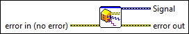
 error in (no error)
—
error in (no error)
—
Describes error conditions that occur before this node runs.  Offset
—
Offset
—
Specifies the DC offset of the signal. The default is 0. The value you wire to this input overrides the value you set in the configuration dialog box.
Phase
—
Specifies the initial phase in degrees of the signal. The default is 0. The value you wire to this input overrides the value you set in the configuration dialog box.
Amplitude
—
Specifies the amplitude of the signal. The default is 1. The value you wire to this input overrides the value you set in the configuration dialog box.
Duty Cycle (%)
—
Specifies the percentage of time a square wave remains high versus low over one period. The default is 50. The value you wire to this input overrides the value you set in the configuration dialog box.
Noise Amplitude
—
Specifies the maximum absolute value the signal can have. The default is 0.6. The value you wire to this input overrides the value you set in the configuration dialog box.
Standard deviation
—
Specifies the standard deviation of the noise you generate. The default is 0.6. The value you wire to this input overrides the value you set in the configuration dialog box.
Spectral amplitude
—
Specifies the magnitude of the frequency domain components of the simulated signal. The default is 0.6. The value you wire to this input overrides the value you set in the configuration dialog box.
Order
—
Specifies the event number of the unit mean Poisson process. The default is 0.6. The value you wire to this input overrides the value you set in the configuration dialog box.
Mean
—
Specifies the interval of a unit rate Poisson process. The default is 0.6. The value you wire to this input overrides the value you set in the configuration dialog box.
Trial probability
—
Specifies the probability that a given trial is TRUE. The default is 0.6. The value you wire to this input overrides the value you set in the configuration dialog box.
One probability
—
Specifies the probability that a given element of the signal is TRUE. The default is 0.6. The value you wire to this input overrides the value you set in the configuration dialog box.
Polynomial Order
—
Specifies the order of the modulo-2 primitive polynomial to use to generate the signal. The default is 0.6. The value you wire to this input overrides the value you set in the configuration dialog box.  Exponent
—
Exponent
—
Specifies the exponent of the inverse-f spectral shape you want. The default is 1. The value you wire to this input overrides the value you set in the configuration dialog box.
Trials
—
Specifies the number of trials performed for each element of the simulated signal. The default is 1. The value you wire to this input overrides the value you set in the configuration dialog box.  Reset Signal
—
Reset Signal
—
Specifies when to reset the signal. The value you wire to this input overrides the value you set in the configuration dialog box.
Seed Number
—
Reseeds the noise sample generator when this value is > 0. The default is –1. If seed is 0, the noise generator does not reseed and resumes producing noise samples as a continuation of the previous noise sequence. The value you wire to this input overrides the value you set in the configuration dialog box.
Frequency
—
Specifies the frequency in hertz of the waveform. The default is 10.1. The value you wire to this input overrides the value you set in the configuration dialog box.  Signal
—
Signal
—
Returns the output signal formatted as dynamic data.  error out
—
error out
—
Contains error information. This output provides standard error out functionality. |
Examples
Refer to the following example files included with LabVIEW.
- labview\examples\Express VIs\Express VI - Amplitude and Level Measurements.vi