Rational Resample (single channel, DBL) VI
- Updated2025-07-30
- 4 minute(s) read
Resamples the input signal X by interpolating X, passing the interpolated signal through an FIR filter, and decimating the filtered signal. Wire data to the X input to determine the polymorphic instance to use or manually select the instance.

Inputs/Outputs
 anti-aliasing?
—
anti-aliasing?
—
anti-aliasing? specifies whether the input signal undergoes lowpass filtering when LabVIEW downsamples the signal. If anti-aliasing? is TRUE (default), this VI protects the resampled signal from aliasing. However, the computation requirements increase during resampling.
reset
—
reset controls the initialization of resampling. The default is FALSE. The first time this VI runs or when reset is TRUE, LabVIEW initializes the internal states of the VI to zero and uses start index to determine when the resampling starts. The next time this VI runs and reset is FALSE, LabVIEW initializes the internal states to the final states from the previous call to this VI. To process a large data sequence that consists of smaller blocks, set reset to TRUE for the first block and to FALSE for all the remaining blocks in continuous resampling.  X
—
X
—
X is the input real signal for resampling. The sampling interval of X is 1.  start index
—
start index
—
start index determines where the resampling starts for the first call to the VI or if reset is TRUE. Set the start index according to the signal after X is interpolated. start index must be greater than or equal to 0. The default is 0.  resample factor
—
resample factor
—
resample factor contains the interpolation factor and the decimation factor for resampling.
 error in (no error)
—
error in (no error)
—
error in describes error conditions that occur before this node runs. This input provides standard error in functionality.
FIR filter specifications
—
FIR filter specifications specifies the minimum values this VI needs to specify the FIR filter.
 Y
—
Y
—
Y returns the resampled signal. The sampling interval of Y is decimation/interpolation.  t0
—
t0
—
t0 returns the time instance for the first sample of each signal in Y.  error out
—
error out
—
error out contains error information. This output provides standard error out functionality. |
 alias rejection (dB)
—
alias rejection (dB)
—
The following steps describe the rational resampling process. Each step corresponds to a numbered section of the following image.
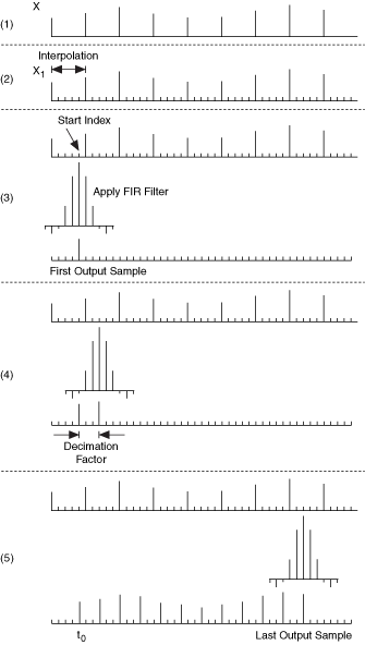
- Input signal X for resampling. The time interval between two adjacent samples is 1.
- Insert zeros between every two adjacent samples to upsample X by the interpolation factor. Let X1 represent the interpolated signal.
- Using a FIR filter, filter X1at the start index to obtain the first output sample. The elements outside the range of the interpolated signal equal zero.
- Move the filter to the position start index + decimation and filter again to obtain the second output sample.
- Repeat step 4, adding each new decimation value until there are not enough samples in X1 for filtering. Store the final samples to internal states and wait for the next signal block. The time interval between two adjacent samples in an output signal is equal to decimation / interpolation. t0 specifies the time of the first output sample.
Examples
Refer to the following example files included with LabVIEW.
- labview\examples\Signal Processing\Signal Operation\Rational Resampling.vi