Wavelet Packet Decomposition (Advanced Signal Processing Toolkit)
- Updated2023-02-21
- 4 minute(s) read
You can approximate the discrete wavelet transform (DWT) using filter banks. When the decomposition is applied to both the approximation coefficients and the detail coefficients, the operation is called wavelet packet decomposition.
The following figure shows the wavelet packet decomposition tree.

The numbers indicate the path of each node. The path is a combination of the characters 0 and 1, where 0 represents lowpass filtering followed by a decimation with a factor of two, and 1 represents highpass filtering followed by a decimation with a factor of two.
Based on the previous figure, you can represent a signal with different sets of sequences, or different decomposition schemes, such as (1, 01, 001, 000), ( 1, 00, 010, 011), or ( 000, 001, 010, 011, 100, 101, 110, 111). As the decomposition level increases, the number of different decomposition schemes also increases.
The DWT is useful in compressing signals in some applications. The wavelet packet decomposition also can compress signals and provide more compression for a given level of distortion than the DWT does for some signals, such as signals composed of chirps.
For example, the wavelet packet decomposition and the DWT with the sym8 wavelet, decomposition level 4, and periodic extension are applied to the Piece Polynomial signal and the Chirps signal. The following figure shows the decomposition of the Piece Polynomial signal. The resulting histogram of the wavelet packet coefficients is similar to the histogram of the discrete wavelet coefficients, meaning that the DWT and the wavelet packet decomposition have similar compression performance for the Piece Polynomial signal.

The following figure shows the decomposition of the Chirps signal. The resulting histogram of the wavelet packet coefficients is more compact than the histogram of the DWT coefficients. Therefore, the wavelet packet decomposition can achieve a higher ratio for signals like the Chirps signal.

Arbitrary Path Decomposition
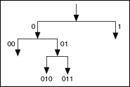
Traditional wavelet packet decomposition iteratively applies the lowpass and highpass filters to both the approximation and the detail coefficients. The arbitrary path decomposition, as a special case of the wavelet packet decomposition, iteratively applies the lowpass and highpass filters to either the approximation or the detail coefficients at each level. You can consider arbitrary path decomposition as a band-pass filter, which you can implement by cascading filter banks. The following figure shows an example arbitrary path decomposition.

In this example, the decomposition path is 011, because the signal first enters a lowpass filter 0, then a highpass filter 1, and finally a highpass filter 1 again. The results on the paths 1, 00, and 010 also can be saved for reconstruction purpose. The paths 1, 00, and 010 define residual paths.
Use the WA Arbitrary Path Decomposition VI and the WA Arbitrary Path Reconstruction VI to decompose and reconstruct a signal according to different paths and wavelet types.
The following figure shows an application of the arbitrary path decomposition in detecting engine knocking due to an ignition-system malfunction.

This example applies the bior3_7 wavelet and the path 11 to the decomposition of the signal that the Engine Knocking Sound graph contains. The Enhanced Sound graph shows the signal reconstructed from the path 11. The high-amplitude components around 0.6, 0.8, and 1.0 in the Enhanced Sound graph indicate where the ignition malfunction of the engine occurs.
Refer to the Engine Knocking Detection VI in the labview\examples\Wavelet Analysis\WAApplications directory for an example of how to use arbitrary path decomposition to detect engine knocking.