MATLAB®, Simulink®, and LabVIEW FPGA: Importing HDL Coder™ Exports into LabVIEW FPGA Designs
Overview
This document provides tutorials on how to import an example model or algorithm written in MATLAB® or Simulink®, generate VHDL using HDL Coder™, import into LabVIEW FPGA, and test on NI FPGA hardware connected to real-world inputs and outputs. NI recommends reading this document for additional context on LabVIEW integration options and using HDL Coder before following the tutorials.
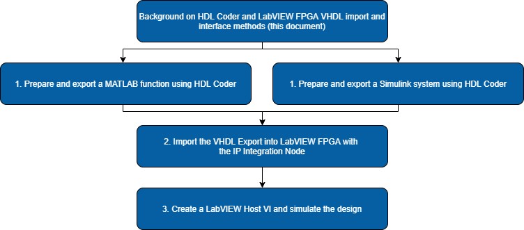
1. Create a VHDL export with HDL Coder and MATLAB or Simulink:
- HDL Coder and LabVIEW FPGA: Modifying and Exporting a MATLAB Function for LabVIEW FPGA
- HDL Coder and LabVIEW FPGA: Modifying and Exporting a Simulink Model for LabVIEW FPGA
2. HDL Coder and LabVIEW FPGA: Importing HDL Coder Exports in LabVIEW FPGA
3. HDL Coder and LabVIEW FPGA: Creating LabVIEW FPGA Host Code and Testing with Simulation
Contents
Requirements
The Software versions below were used in the creation of the tutorials. Other versions may work with differences in appearance.
- LabVIEW 2019
- LabVIEW 2019 FPGA Module
- LabVIEW 2019 FPGA Compilation Tool for Vivado 2017.2
- NI R Series Multifunction RIO 19.1
- MATLAB R2019a
- Simulink R2019a
- Fixed-Point Designer™
- MATLAB Coder™
- HDL Coder
- Signal Processing Toolbox™ recommended
- DSP System Toolbox™ recommended
- HDL Verifier™ recommended
LabVIEW FPGA Integration Options
Before beginning the integration of a design, you need to make several choices on how to integrate the function in LabVIEW FPGA. NI recommends performing research on these options using the available documentation to best make an educated decision. This section summarizes some of these options as a starting point.
Interface Types
The LabVIEW FPGA Module supports several interface types. While these may not be required depending on the requirements of a specific design, they make the integration of external functions into LabVIEW FPGA more robust and portable. The following are a subset of possible options:
- Valid In and Valid Out signals
- AXI Protocol to LabVIEW FPGA
For the tutorials in this series, the Valid In and Valid Out option will be used. This option is the simplest to implement as it requires minimal design changes to existing functions and minimal additional signals. However, this option also assumes nothing stalls the execution of the design. Specifically:
- The integrated function does not need to wait on downstream functions to be ready before outputting data.
- The integrated function is always ready to accept input data.
When integrating functions or working with a design that does not meet these requirements, NI recommends using the handshaking interface. For more information on other integration options, refer to the following resources:
- The NI LabVIEW High-Performance FPGA Developer's Guide
- Interfacing AXI IP in FPGA VIs (FPGA Module)
- Scheduling Timing Using Handshaking Signals (FPGA Module)
Integration Methods
The LabVIEW FPGA Module provides two main methods to integrate external IP: Component-Level Intellectual Property (CLIP) and the Intellectual Property Integration (IP Integration) Node, each of which has different use cases, advantages, and disadvantages. Refer to the following guidelines for information about choosing between the two methods:
- Use the IP Integration Node to integrate IP that is more functional and algorithmic in nature or works as a processing function where some input is provided, and the IP generates some output on every call.
- Use the CLIP to integrate IP that acts as an independent, asynchronous component, such as IP that interacts with multiple parts of your application or an interface to some external digital component such as memory, SPI, or I2C.
The above is simply a high-level overview. More comparisons and best practices can be found in The NI LabVIEW High-Performance FPGA Developer's Guide and the LabVIEW FPGA Module Help. NI recommends referring to Integrating Third-Party IP (FPGA Module) for a complete comparison between the options and a list of supported file types.
In this tutorial series, the simple FIR Filters will be used to demonstrate the process. This type of design aligns more closely with the functional or algorithmic nature of the IP Integration Node and will follow that workflow. In fact, most HDL Coder exports fit this functional paradigm and should be imported using the IP Integration Node.
Using HDL Coder
While many functions may be exported to an HDL representation using HDL Coder, only some Simulink blocks and MATLAB functions are supported by the export process. In addition, it’s important to consider designs from the hardware context. A design that runs efficiently in a software implementation may not translate well to the physical hardware representation used by FPGA devices. NI recommends reviewing the Getting Started with HDL Coder documentation before attempting to create a custom function or model for HDL code generation.
Export Methods
HDL Coder provides several options for code generation targets. Of these, two options result in code that is fully usable in LabVIEW FPGA:
- Generic ASIC/FPGA – This option generates target-independent generic VHDL which can be used on any FPGA target.
- IP Core Generation for Generic Xilinx Platform – This option allows generation of board-independent IP Cores with AXI4, AXI4 Stream, or AXI4-Lite interfaces. Note that this option requires a local installation of Xilinx Vivado.
The tutorials demonstrating the process will focus on the Generic ASIC/FPGA option as it does not require any additional software or knowledge of AXI interfaces. For more information on the IP Core Generation workflow, refer to IP Core Generation in the official HDL Coder documentation.
Note: If you use the IP Core Generation option, NI recommends using the Xilinx Vivado version that installs with the LabVIEW FPGA Module Xilinx Compilation Tool for Vivado. This ensures that the toolchain used is the same one that LabVIEW FPGA uses for FPGA compilation. The path to this tool is typically as follows: <LabVIEW FPGA installation drive>\NIFPGA\<Vivado version>\bin\vivado.bat.
Obtaining or Creating MATLAB Code for HDL Coder
MATLAB functions written for HDL Coder export have differences and limitations when compared to a typical MATLAB function. While both are similarly formatted, functions which will be used with HDL Coder should be written with the understanding that the code will be converted to an HDL representation. This approach helps to ensure that the HDL export can meet performance requirements – such as speed or resource usage – once imported into LabVIEW FPGA.
When designing or converting a MATLAB function for HDL code generation, keep the following guidelines in mind:
- Use persistent variables to ensure data persists between function calls. These variables should be used to represent state data or registers.
- Add variables to the function to represent additional signals such as handshaking.
Note: HDL Coder provides options to add Reset and Clock Enable signals. - Use MATLAB functions that are supported by HDL Coder. Refer to Functions Supported for HDL Code Generation — Categorical List for a list of supported functions.
- Use a testbench that matches the real-world data ranges and types to be used. This enables the fixed-point conversions to choose optimal numeric representations.
- Refer to Hardware Modeling with MATLAB Code and Guidelines for Efficient HDL Code for example functions and other best practices.
Obtaining or Creating Simulink Code for HDL Coder
Simulink designs to be exported by HDL Coder should follow the recommended HDL Modeling Guidelines for models to ensure that everything is supported and exported efficiently. While it is possible to export Simulink code without keeping these in mind, the export will be more efficient if you take the hardware architecture into consideration during the design process.
Keep the following recommendations in mind when creating and modifying Simulink models for HDL code generation.
- Design Simulink models with blocks that are compatible with HDL Coder. Simulink supports only specific blocks when exporting a system and you can configure the Library Browser to show only these blocks as described in Show Blocks Supported for HDL Code Generation.
- Check existing models with the HDL Model Checker or HDL Coder checks in the Model Advisor. This analyzes the design and highlights compatibility issues and possible improvements. See Model Compatibility Checks and Getting Started with the HDL Model Checker for more information.
- Add new inputs and outputs to represent additional signals such as handshaking. It might be necessary to add Unit Delay blocks to ensure signals are synchronized.
Note: HDL Coder provides options to add Reset and Clock Enable signals. - Use fixed-point data types or Fixed-Point Designer to prepare and convert existing Simulink models to fixed-point representations. Fixed-point data types typically have better performance in FPGA designs compared to floating-point data types.
HDL Workflow Advisor and Scripting
When exporting a design to HDL using HDL Coder, you can manage the process with either the HDL Workflow Advisor or through direct functions and scripting. NI recommends starting with the HDL Workflow Advisor when exporting code for the first time to better understand the available options. For an example of how to script HDL Coder, see Generate HDL Code from MATLAB Code Using the Command Line Interface.
Tips and Tricks
- Handshaking or interface signals are recommended even when a function is asynchronous or may not require multiple clock cycles. This ensures that if registers or pipelining are inserted later due to configuration changes in the HDL Coder export, LabVIEW FPGA will still recognize the data only when valid.
- For fine-grained control over register locations and pipelining, MATLAB allows the explicit declaration of pipelines around expressions in the function. Refer to Pipeline MATLAB Expressions for more information.
- HDL Coder allows the use of pipelining and distributed pipelining to improve the timing of Simulink subsystems. Refer to Distributed Pipelining: Speed Optimization for more information.
- It’s possible to generate HDL code with AXI Stream Signals added automatically by HDL Coder.
- When working with FPGA designs, it’s typical to encounter compilation errors due to resource usage or timing requirements. For descriptions of common compilation errors encountered in LabVIEW FPGA, refer to Interpreting Common Xilinx Compilation Errors in the LabVIEW FPGA Module.