Synchronized Instruments
PXI Oscilloscopes of the same model are automatically hardware synchronized across multiple devices in InstrumentStudio software to serve applications requiring high channel density. Using hardware-timed triggers over the PXI backplane, they can also handshake with other types of instruments in the chassis.

CableSense™ Technology
Using principles similar to a traditional time-domain reflectometer (TDR) on a real-time oscilloscope within your test system, you can detect changes from a known, golden setup without having to alter the connections themselves.
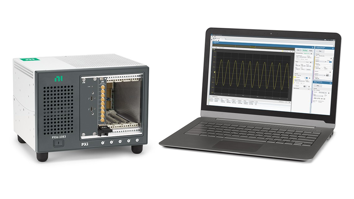
InstrumentStudio™ Interactive Software
PXI Oscilloscopes are shipped with an interactive, multi-instrument soft front panel called InstrumentStudio for ready-to-run configuration and measurements. You can also monitor and debug the instrument in parallel with running code.
Deep Onboard Memory
PXI Oscilloscopes feature deep onboard memory, capable of storing multiple acquisitions from single channels or parallel acquisitions from multiple channels on the same device, and also benefit from the high-speed streaming capabilities of the PXI platform.
Recommendations for First-Time Users
PXI Oscilloscope Bundle
The PXI Oscilloscope Bundle is a preconfigured set of one of NI’s most popular, high-quality oscilloscopes and a Thunderbolt™-controlled chassis so that you can get started with ease.
Featured Content
What Is a Reconfigurable Oscilloscope?
New test applications require more intelligent oscilloscopes to detect complex signal conditions and process data to reduce test times.
Select the Right Oscilloscope Probe for Your Application
Explore single-ended and differential voltage probe options as well as current probes in order to take your best oscilloscope measurement.
Using a Modular Oscilloscope in Your Test System
Learn how the flexibility of modular oscilloscopes and evolving nature of the PXI platform can set you up for long-term success with your test system.
Application Resource
Fundamentals of Building a Test System
Defining a test strategy and planning system investments are critical to reducing cost, optimizing your test-investment life cycle, and maximizing efficiency. Learn test strategies, best practices, and design tradeoffs for your test systems.
Related Products
PRODUCT SUPPORT RESOURCES
Support Library
Explore a wide range of support content, including examples and troubleshooting information.