Developing LabVIEW Plug and Play Instrument Drivers
Overview
This document, which describes the standards and practices for LabVIEW Plug and Play drivers, is intended for driver developers and describes the standards for structuring VIs, instrument I/O, style, and error reporting. It also describes instrument driver components and how to integrate these components. In addition, this document describes a process for developing useful instrument drivers.
Other resources for instrument driver developers include the instrument driver templates and the Instrument Driver Guidelines, both of which are available from the NI Instrument Driver Network (ni.com/idnet).
To use this document, you should have a basic understanding of instrument control and be familiar with the operation of LabVIEW. You also should be familiar with the with Virtual Instrument Software Architecture (VISA) application programming interface (API).
Contents
- What Is a LabVIEW Plug and Play Instrument Driver?
- LabVIEW Plug and Play Instrument Driver Model
- LabVIEW Instrument Driver Development
- Driver Support Libraries
- Important Considerations
- Conclusion
- Related Links
What Is a LabVIEW Plug and Play Instrument Driver?
A LabVIEW Plug and Play instrument driver is a set of VIs that control a programmable instrument. Each VI corresponds to an instrument operation, such as configuring, triggering, and reading measurements from the instrument. Instrument drivers help users get started using their instrument from their computer and saves them development time and cost because users do not need to learn the programming protocol for each instrument. With open-source, well documented instrument drivers, end users can customize their operation for better performance. A modular design makes the driver easier to customize.
Using a standard architecture for all LabVIEW instrument drivers has the following benefits:
- Improves the consistency of instrument drivers for the benefit of end users.
- Improves the quality of the drivers.
- Minimizes duplicated effort.
- Improves ease of use for end users by providing a consistent methodology for using instrument drivers from a variety of sources.
- Streamline the instrument driver development process for the benefit of instrument driver developers.
The LabVIEW Instrument Driver Network contains instrument drivers for a variety of programmable instruments, including GPIB, USB, TCP/IP, VXI, RS-232, and PXI instruments. Instrument drivers contain high level VIs with intuitive front panels, so end users can quickly test and verify the remote capabilities of their instrument. They do not need to know low-level instrument control and instrument-specific commands and syntax. Users create instrument control applications by building VIs using instrument driver VIs as subVIs on their block diagrams.
LabVIEW Plug and Play Instrument Driver Model
Many programmable instruments have a large number of functions and modes. With this complexity, it is necessary to provide a consistent design model that aids both instrument driver developers as well as end users who develop instrument control applications. The LabVIEW Plug and Play instrument driver model contains both external structure and internal structure guidelines. The external structure shows how the instrument driver interfaces with the user and to other software components in the system. The internal structure shows the internal organization of the instrument driver software module.
Instrument Driver External Structure
An instrument driver consists of the API VIs the user calls from a higher level application. The figure below illustrates how the instrument driver interacts with the rest of the system.
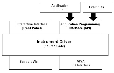
Figure 1: LabVIEW Instrument Driver External Structure
The external structure illustrates how the instrument driver presents both an interactive interface and a programming interface. The application programming interface (API) is the set of user-callable instrument driver VIs used in end-user systems. For example, a manufacturer test system might make instrument driver calls to communicate with a multimeter or an oscilloscope.
The end user learns about the API through the instrument driver front panels. By interactively running the front panels of the instrument driver VIs, end users understand how each control affects the instrument. After they understand the settings, end users can incorporate the instrument driver VIs in their application.
The Virtual Instrument Software Architecture (VISA) I/O interface is the set of LabVIEW functions the driver uses to communicate with the instrument hardware. VISA is an established standard instrumentation interface that controls GPIB, USB, serial and other instrument buses. Refer to the LabVIEW Help for descriptions of VISA functions and controls.
Support VIs are VIs that you do not intend the end user to access directly. Therefore, support VIs are not part of the instrument driver API. For example, instrument drivers often call the Default Setup VI during initialization to set the instrument in a state that allows for robust instrument control by the rest of the instrument driver VIs. Only the Initialize and the Reset VIs use the Default Setup VI as a subVI, so it is considered a support VI.
Instrument Driver Internal Design Model
The internal structure of the instrument driver defines the organization of the instrument driver VIs. All user-accessible API VIs are organized into a modular hierarchy based on instrument functionality.
The figure below shows the internal structure of LabVIEW instrument drivers. End users have the necessary granularity for controlling instruments properly in applications. For example, end users can initialize all instruments once at the start, configure multiple instruments, and then trigger several instruments simultaneously. Also, they can initialize and configure an instrument once, and then trigger and read from the instrument several times.
For end users, the model provides a consistent instrument driver model. After users understand one instrument driver, they can apply that knowledge to other LabVIEW instrument drivers.
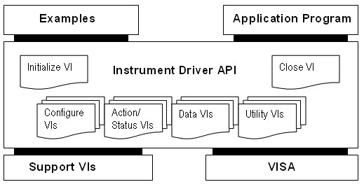
Figure 2: LabVIEW Instrument Driver Internal Structure
Instrument Driver API VIs
Instrument driver API VIs are organized into the following six categories:
Initialize -- All LabVIEW instrument drivers should include an initialize VI. This VI establishes communication with the instrument, so it is the first instrument driver VI called. Optionally, the VI performs an instrument identification query and reset operations. It also can place the instrument in its default power on state or in some other state.
Configuration -- Configuration VIs are a collection of software routines that configure the instrument to perform specific operations. Usually instrument driver APIs include several configuration VIs, The number of configuration VIs for an instrument driver depends on the unique capabilities of the instrument. After you call these VIs, the instrument is ready to take measurements or stimulate a system.
Action/Status -- There are two types of action/status VIs. Action VIs cause the instrument to initiate or terminate test and measurement operations. These operations include arming a trigger or generating a stimulus. These VIs differ from the configuration VIs because they do not change the instrument settings. Instead, they command the instrument to carry out an action based on its current configuration. Status VIs obtain the current status of the instrument or the status of pending operations. Status VIs are usually created when required by other functions.
Data -- The data VIs transfer data to or from the instrument. Examples include VIs for reading a measured value or waveform, and VIs for downloading waveforms or digital patterns to a source instrument. The specific routines in this category depend on the instrument.
Utility -- Utility VIs perform a variety of auxiliary operations, such as reset and self-test, and can include other custom routines, such as calibration or storing and recalling instrument configurations.
Close -- The close VI terminates the software connection to the instrument. All LabVIEW instrument drivers should include a close VI.
Each category of VIs, with the exception of initialize and close, contains several modular VIs. Much of the important work in developing an instrument driver lies in the initial design and organization of the instrument driver API VIs.
You can download template VIs from NI, and customize them to perform operations common to almost all instruments, such as initialize, close, reset, self-test, and revision query. The template VIs contain modification instructions for their use in a specific instrument driver for a particular instrument. Refer to the LabVIEW Instrument Driver Templates section for more information about customizing template VIs.
In addition to these common functions, you add additional VIs to perform instrument-specific operations. The specific VIs you develop depend on the unique capabilities of your instrument. However, whenever possible, adhere to the six instrument driver VI categories.
Using the internal design structure as shown in Figure 2, an end user can combine instrument driver VIs to create applications. The block diagram in the figure below shows how instrument drivers API VIs programmatically control the HP34970A acquisition system.
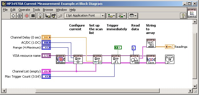
Figure 3: HP34970A Current Measurement Example VI Block Diagram
Figure 4 shows the block diagram of one of the instrument driver API VIs, which use built-in LabVIEW functions and VISA functions to build command strings and send them to the instrument. The VISA functions perform device management, standardized instrument I/O, and error handling. The specific VI in Figure 4 below creates a command string by combining string formatting operations, then wiring the resulting string into the VISA Write function. The VISA Write function sends the command string to the instrument. The VISA Read function returns the response string from the instrument. The response string then gets formatted into a numeric array for use in the end user's application. The reformatting of the response string is beneficial to the user by allowing them to view the response data in a format that they prefer. The Error Query VI checks for errors and updates error cluster.
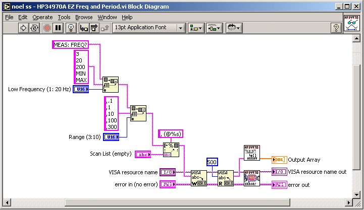
Figure 4: Creating a Command String
Additional VIs Distributed with the Instrument Driver
In addition to the API VIs described by the internal structure, an instrument driver also includes example VIs and a VI Tree VI.
Instrument Driver Example VIs
All instrument drivers include example VIs. These examples show users how to combine the instrument driver VIs for basic test and measurement operations with the instrument. They demonstrate test and measurement functionality by configuring the instrument for a common mode of operation, triggering, and taking measurements. Example VIs also verify communication with the instrument. These examples should be added to the NI Example Finder through the creation of a *.bin3 file. The figure below shows the front panel of the HP34970A Current Measurement Example VI.
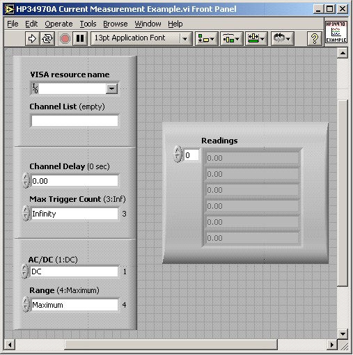
Figure 5: Front Panel of the HP34970A Current Measurement Example VI
VI Tree VI
Most users access instrument driver VIs from the LabVIEW Functions palette. However, VI Tree VIs let end users view the entire instrument driver hierarchy at once. The VI Tree VI is a non-executable VI designed to show the functional structure of the instrument driver, as shown in the figure below.
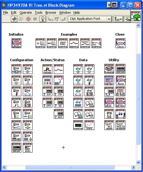
Figure 6: Block Diagram of the HP34970A VI Tree VI
LabVIEW Instrument Driver Development
This section describes the procedure for developing a LabVIEW Plug and Play instrument driver. The ideal LabVIEW instrument driver allows an end user to control all functionality of the instrument. Because it is not possible to specify required functionality of all different instrument types, such as multimeters, counter/timers, this section focuses on the architectural guidelines for all drivers. Use this information to help organize and package your drivers in a consistent way while still implementing functionality unique to your instrument.
Complete a three-step process to develop a LabVIEW instrument driver. In Step 1, you design the instrument driver structure. In Step 2, you use the Instrument Driver Project Wizard to create new instrument driver VIs. In Step 3, you add developer-defined VIs and create example VIs.
Step 1. Design the Instrument Driver Structure
The ideal instrument driver does what the user needs -- no more and no less. No particular type of driver design is perfect for everyone but by carefully studying the instrument and grouping controls into modular VIs, you can satisfy most of your users.
When the number of programmable controls in an instrument increases, so does the need for modular instrument driver design. Do not try to implement all of the functionality of an instrument with a single VI. However, do not design an instrument driver where each VI controls a single feature. This approach could result in an API with hundreds of VIs. Also, this could force the end user into understanding instrument-specific rules for command order and interaction. Modular design simplifies the programming needed to control the instrument.
Devise the overall structure of your instrument driver before you build the individual VIs. Design an instrument driver with the application and end user in mind.
Understanding the instrument is critical to the design process
The following steps outline one approach to developing the structure for a LabVIEW instrument driver.
- Familiarize yourself with the instrument operation. Read the operating manual thoroughly. Learn how to use the instrument interactively before you attempt any VI development.
- Use the instrument in an actual test configuration to get practical experience. The operating manual might explain how to set up a simple test.
- Study the programming section of the manual. Read the instruction set to learn about the controls and functions available and their organization. Decide upon the best features for programmatic use.
- Examine existing instrument drivers to see if you can find any that control similar instruments. Often instruments from the same family have similar programming command sets that you can modify for your instrument.
- Look for controls that are used together to perform a single task or function to aid in developing the structure of the driver. Often, the sections of the manual correspond to the functional groupings of an instrument driver.
Develop the driver structure by organizing instrument commands
The organization of an instrument driver defines the hierarchy and overall relationship of the instrument driver component VIs.
There are two types of API VIs in an instrument driver: those that are common to all instruments and those that expose the unique capabilities of the instrument. Template instrument driver VIs (initialize, close, reset, self-test, revision query, and error query) perform these common operations. You, as the instrument driver developer, define the VIs that expose the unique capabilities of the instrument. Some instrument drivers might define additional categories, such as “route” or “scan” for switch instruments.
Group common and developer-defined VIs into categories. A category is a group of VIs that perform similar operations. The most common categories of VIs are configuration, action/status, data, and utility.
The following table shows an example instrument driver organization for a simple oscilloscope. At the highest level of the hierarchy, you see the template VIs (initialize and close) and the typical VI categories.
Table 1: Organization Example for a Simple Oscilloscope.
| VI Hierarchy | Type |
|---|---|
| Initialize VI | (Template) |
| Example VIs Autosetup and Read Waveform Example | (Developer Defined) |
| Configuration VIs Autosetup Configure Vertical Configure Horizontal Configure Trigger Configure Acquisition Mode | (Developer Defined) (Developer Defined) (Developer Defined) (Developer Defined) (Developer Defined) |
| Data VIs Read Waveform Read Measurement Advanced VIs Initiate Fetch Waveform Fetch Measurement | (Developer Defined) (Developer Defined) (Developer Defined) (Developer Defined) (Developer Defined) |
| Utilities VIs Reset Self-Test Revision Query Error Query | (Template) (Template) (Template) (Template) |
| Close VI | (Template) |
Design Example
Consult the organizational information available in most instrument manuals to help you decide which parameters to include on an instrument driver VI. In particular, the programming section of the manual might group the commands into sections, such as configuring a measurement, triggering, reading measurements, and so on. Use these groupings as a model for the driver hierarchy. Look for controls that are used together to perform a single task or function to help you develop a structure for the driver. A modular driver contains individual VIs for each of the control groups.
The table below shows how instrument commands for a simple DMM might correspond to developer-defined instrument driver VIs.
Table 2: Relationship of Manual Sections and Commands with Instrument Driver VIs.
| Virtual Instrument Terminals | Instrument Commands |
|---|---|
| Initialize ID Query? Reset? | Input/Output Configuration *IDN? *RST |
Config Measurement Measurement Function | Measurement Configuration SENS:FUNC <function selection> <function selection>:RANGE; <function selection>:RES; <function selection>:NPLC; |
Config Trigger Trigger Source | Triggering Operations TRIG:SOUR TRIG:DEL TRIG:COUN SAMP:COUN |
| Read Measurement Readings | Measurement Reading Use the following commands to retrieve measurements INIT; FETCH; |
While the instrument manual can provide a great deal of information about how to structure the instrument driver, do not rely on it exclusively. Your knowledge of using the instrument should be your main guide. Often, you should place commands from several different command groups in a single VI. At other times you must take one group of commands from the manual and divide it into two or more VIs. Consider how an instrument manual groups the trigger configuration commands with the commands that actually perform trigger arming and execution. In this case, separate the commands into two VIs -- one that configures the trigger and one that arms or triggers the instrument.
Step 2. Use the Instrument Driver Project Wizard to Create a New Instrument Driver
After you design the LabVIEW instrument driver structure, use the Instrument Driver Project Wizard to create a new instrument driver, and then modify the new instrument driver VIs to work with your instrument.
Using the Instrument Driver Wizard
In LabVIEW 8.x and later, the Instrument Driver Project Wizard can be used to create a new instrument driver project.
Complete the following steps to create an Instrument Driver using the Instrument Driver Wizard:
- From LabVIEW Getting Started Window, select Tools»Instrumentation»Create Instrument Driver Project to launch the Instrument Driver Project Wizard.
- Select New driver from template from the Project Type menu and select the type of instrument from the Source Driver menu.
- Select Next.
- Create a Driver Identifier. It should be something practical.
- Select Next.
- Select icon color and type.
- Select Finish. This will bring up the Project Window and LabVIEW Help.
Step 3. Add Instrument Driver API VIs
Add the developer-defined API VIs that define the functionality of the instrument driver and access the unique capabilities of the instrument.
Using the Instrument Driver VI Wizard
The Instrument Driver VI Wizard can create additional VIs that the instrument supports. If you created a driver from a class template, such as the Digital Multimeter template, the instrument probably supports additional functionality not covered by the class template. You should create additional VIs for each supported feature, using the existing VIs and structure for guidance. For example, oscilloscopes often have many types of triggers but the Oscilloscope template only includes support for edge triggering. If the instrument supports additional types of triggers, add this functionality with additional instrument driver VIs.
Complete the following steps to create an Instrument Driver using the Instrument Driver Wizard:
- Open an Instrument Driver Project.
- Right-click a LabVIEW instrument driver project library (.lvlib) in the Project Explorer Window and select New»Instrument Driver VI from the shortcut menu to display the Instrument Driver VI Wizard.
- On the Start page of the Instrument Driver VI Wizard, select one of the following options and click the Next button.
- Create from an instrument driver template VI—Creates the instrument driver VI from a template VI.
- Copy from an existing VI—Copies and configures an existing instrument driver VI and its subVIs.
- Configure your own VI—Configures an instrument command, specifies how to parse a response, interacts with connected instruments, and generates the corresponding instrument I/O and string formatting/parsing code into a new instrument driver VI.
- Add a blank VI—Creates an instrument driver VI that contains only a VISA resource name control and indicator and an error cluster control and indicator.
- On the second page of the wizard:
- If you selected Create from an instrument driver template VI on the Start page, select a VI from the available instrument driver VI templates on the Clone from Template page and click the Next button.
- If you selected Copy from an existing VI on the Start page, click the Browse button on the Browse for VI page to navigate to and select the VI you want to add to the project and click the Next button.
- If you selected Configure your own VI on the Start page, select Configuration VI or Measurement VI on the Select VI type page and click the Next button. Select Configuration VI to create a VI that sends a command to the instrument. Select Measurement VI to create a VI that sends a command to the instrument and then reads a response from the instrument.
- If you selected Add a blank VI on the Start page, continue to step 6.
- If you selected Configure your own VI on the Start page, configure the Control setup page and click the Next button. Otherwise, continue to the next step.
- Select the appropriate data type for each parameter from the Data type pull-down menu.
- Set a default value for each parameter in the numeric box next to the Data type pull-down menu.
- Verify the configured command string in the Command preview text box.
- If you selected Configuration VI on the Select VI type page, select the instrument from the pull-down menu in the Test the Command section. If you selected Measurement VI on the Select VI type page, click the Next button and select the instrument from the pull-down menu in the Test the Command section.
- Click the Run Test button to test the command you configured. LabVIEW sends the command in the Command preview text box to the instrument and shows the number of bytes written to the instrument in the Bytes written box. If the command succeeds, the light turns a brighter green. If VISA returns an error, the light turns red. Click the Explain Error button to display the errors. If you selected Measurement VI on the Select VI type page, LabVIEW reads the response from the instrument and displays it in the Response text box. You can select the data type of the response in the Configure response data type section.
- On the VI Properties page, edit the VI name, path, icon, and description and click the Next button.
- On the Summary page, review the information about the new VI and click the Finish button to add the instrument driver VI and any subVIs to the instrument driver project and open the VI. If you created the VI from a template VI or an existing VI, LabVIEW renames subVIs that have the same name but a different connector pane as an existing VI in the project library. LabVIEW does not copy subVIs that have the same name and the same connector pane as an existing VI in the project library. The new VI uses the existing VIs in the project library in place of any subVIs that LabVIEW did not add.
• VIs: Names and Properties
• Control/Indicators: Naming and Data Representation
• VI Front Panels
• Icon & Connector Panes
• Block Diagrams
• Documentation
After you modify each VI, create Functions palette menus so customers can install, access, and use instrument drivers from the Functions palette. For consistency, instrument drivers should appear in the Instrument Driver VIs subpalette. Within the subpalette, the instrument VIs should have the same organization as the internal design model as shown in the figure below.
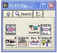
Figure 7: Example Subpalette for the FL45
Front Panel Style
In addition to the controls required to operate the instrument, the front panel should include the VISA resource name control, VISA resource name out indicator, error in control, and error out indicator. Refer to the Drivers Support Libraries section for more information about the VISA session handles. In LabVIEW 7.1 or earlier, refer to Chapter 6 of the LabVIEW User Manual (linked below) for more information about the error in and error out parameters. In LabVIEW 8.0 or later, refer to the Handling Errors topic in the LabVIEW Help (linked below).
Use the following style guidelines to ensure uniformity with other LabVIEW front panels as you design front panels. Refer to the Control/Indicators: Naming and Data Representation and Front Panels section of the Instrument Driver Guidelines for the complete requirements and recommendations for creating instrument driver front panels.
- Use the default (Application) font for all labels. LabVIEW includes this font, so it is available to all other users.
- Format control and indicator names as bold. Capitalize the first letter of each word in the control labels, such as Configure Trigger Source. VISA resource name, error in, error out, and well-known acronyms such as AC or FM are exceptions.
- Enclose default information in plain text in parentheses in the control label so the defaults appear in the Context Help window. This aids in wiring to the VI on the block diagram. For example, label a function selector ring control with a default of DC volts at item zero as Function (0:DCV), and label a Boolean switch that defaults to TRUE indicating automatic enabled as Auto Trigger Delay (T:On).
- Place the VISA resource name control in the upper left, the VISA resource name indicator in the upper right, the error in control in the lower left and the error out control in the lower right.
- Edit all control and indicator descriptions. Refer to the LabVIEW Help for more information about creating control descriptions.
Icon and Connector Pane
Reserve the upper left terminal of the connector pane for the VISA resource name control and the upper right terminal for the VISA resource name out indicator. Reserve the lower left terminal for the error in control and the lower right terminal for the error out indicator to simplify wiring to subsequent error terminals. Select a connector pane pattern that has more terminals than the number of controls and indicators because you might add controls or indicators to the connector pane at a later time. This precaution prevents you from changing the pattern and replacing all instances of calls to a modified subVI. Place inputs on the left and outputs on the right to promote a left-to-right data flow on the block diagram.
Use meaningful icons for every VI. Use the icons found in the Icon Art Glossary whenever possible. Also, you can borrow icons from similar VIs in other instrument drivers or use the icon library Icon256.vi located in the labview\examples\instr\insticon.llb directory. Include the instrument driver prefix at the top of the icon so users can identify VIs from the driver API. Create an icon using glyphs and images that represent the VI functionality. The figure below shows sample configuration icons from the Icon256.vi.
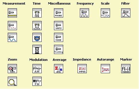
Figure 8: Sample Icons
Refer to the Icon & Connector Pane section of the Instrument Driver Guidelines for specific requirements and recommendations for creating meaning icons and designing connector panes.
Block Diagram
After you design the front panel, create the block diagram. Use the Format into String function to create instrument command strings. This expandable function formats multiple values and multiple data types into a string. Double-click the function to enter format commands using the Format Strings dialog box. Also, use the Append True/False String and Pick Line functions to manipulate strings. For example, use the Append True/False String function to convert the value from a front panel Boolean to a string. This function selects the proper string and concatenates it to the command string in one step. Use the Pick Line function to convert a text ring value to a string. This function selects the proper string based on the label value and concatenates it with the command string. Refer to the LabVIEW Help (linked below) for descriptions of these functions. The block diagram in the figure below demonstrates the preferred methods for building command strings.
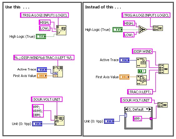
Figure 9: Techniques for Building Strings
Many instruments comply with the Standard Commands for Programmable Instruments (SCPI) programming command set and syntax. These SCPI-based instruments let you join multiple commands together to send in one I/O write operation. The String functions described above let you build strings that include multiple commands. Wire the combined string to the VISA Write function.
The block diagram is the primary way end users learn how the VI works, so it is important to make the block diagrams as easy to read as possible. Most of the recommendations for instrument driver block diagrams are similar to best practices for all LabVIEW applications, which include following a left-to-right layout of the diagram, minimizing bends in the wires, and using efficient and consistent coding techniques. Refer to the Block Diagram section of the Instrument Driver Guidelines for specific requirements and recommendations for creating an instrument driver block diagram.
The block diagram in the figure below adheres to the requirements and recommendations detailed in the Instrument Driver Guidelines.
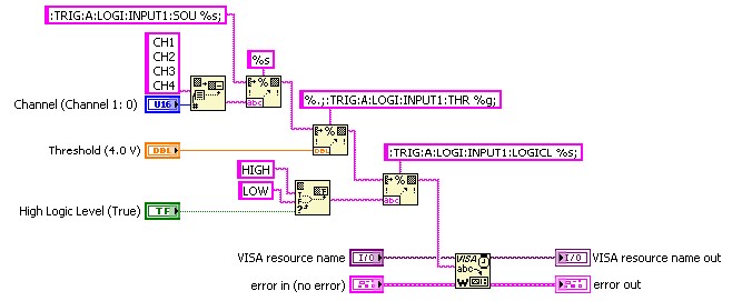
Figure 10: Simple Block Diagram that Follows Style Guidelines
See Also:
LabVIEW User Manual
LabVIEW Help: Handling Errors
Driver Support Libraries
LabVIEW tools for instrument driver development include a library of template VIs that serve as a starting point for creating your own drivers, the Instrument Driver Project Wizard that customizes those templates, VISA functions to perform the instrument I/O, icon libraries to aid in creating meaningful icons, and support files and functions. This section describes the VISA functions and the Instrument Driver Template VIs.
VISA
The VISA functions contain the I/O interface used by instrument drivers to communicate with programmable instruments. VISA is a single interface library for controlling VXI, GPIB, serial, TCP/IP, and other types of instruments. Refer to the VISA VIs and Functions topic of the LabVIEW Help (linked below) for descriptions of VISA functions and controls.
The front panel of most instrument driver VIs include a VISA resource name control and a VISA resource name out indicator. These controls and indicators pass session information between instrument driver subVIs. The VISA resource name identifies the resource on which the VI operates. It also differentiates between different sessions of the instrument driver.
VISA resource name is a unique identifier reference to a device I/O session (except for the Initialize VI). It identifies the device with which the VI communicates and passes all necessary configuration information required to perform the I/O.
VISA resource name out contains the same identifier information as VISA resource name. It passes the reference out of the VI and into other subsequent VIs that access the same instrument. Wiring VISA resource names together establishes data dependencies.
You also pass the VISA resource name into and out of VISA functions on the block diagram.
Instrument Driver Template VIs
The LabVIEW instrument driver templates, located in the instr.lib folder, contain a set of VIs common to most instruments. NI updates these templates periodically, and includes them in the latest version of LabVIEW. Use these VIs as a starting point for your instrument driver development. The templates have a simple, flexible structure, and they establish a standard format for all LabVIEW drivers.
The template VIs contain instructions for modifying the VIs for a particular instrument. Use the template VIs with both message-based instruments (GPIB, VXI, and serial) and VXI register-based instruments. Because the templates were designed for IEEE 488.2 compatible instruments, minimal modifications are needed for IEEE 488.2 compliant instruments. For other instruments, use the template VIs as a shell or pattern for your VIs by substituting your instrument-specific commands where applicable.
See Also:
LabVIEW Help: VISA VIs and Functions
Important Considerations
Documenting VIs
Document the VIs you create so information appears in the LabVIEW Context Help window for each instrument driver. Refer to the Documenting VIs topic of the LabVIEW Help (linked below) for more information about documenting VIs.
Select Help»Show Context Help to access the Context Help window. When you move the cursor over front panel or block diagram objects, or over the icon in the upper right corner of the front panel or block diagram, a description for that object appears in the Context Help window that includes documentation.
Also, use free labels on the front panel and the block diagram to aid the user. On the block diagram, show all terminal labels (plain text) and color the borders transparent. Use bold text in free labels in that appear in Case and Sequence structures to make the comment stand out and the VI easier to understand and modify.
Error Reporting
Error reporting in instrument drivers is similar to error reporting in most other LabVIEW applications. The VISA functions check the Boolean state of the error in cluster to determine if a previously executed VI or function generated an error. If the VI or function detects an error, the VISA function does not perform its usual operation. Instead, it passes the error information to the error out cluster without modification. If the VI or function does not detect an error, the VISA function executes normally and determines whether it generated an error. If so, the function returns new error information in the error out cluster. Otherwise, the function returns the error in information in the error out cluster. The first error triggers subsequent VIs not to execute (or some other action defined by the user) and the error code and the source of the error propagate to the top-level front panel. Additionally, warnings (error codes and source messages with the error Boolean set to FALSE) pass through without triggering error actions.
In addition to VISA error codes, the error and warning codes listed in the table below are reserved for instrument drivers. The instrument driver VIs should return these codes when the appropriate conditions occur. You might see error codes like -1300 for instrument specific errors in older instrument drivers and older instrument driver templates. However, use the codes in the following table to ensure compliance with instrument driver standards.
Table 3: Instrument Driver Error Codes Decimal Code
| Decimal Code | Hex Code | Meaning |
|---|---|---|
| 0 | 0 | No error: the call was successful |
| 1073481728 to 1073483775 | 3FFC0800 to 3FFC0FFF | WARNING: Developer defined warnings |
| -1074003951 | BFFC0011 | ERROR: Identification query failed |
| -1074000000 | BFFC0F80 | ERROR: Instrument Defined Error |
| -1073999873 to -1074001919 | BFFC0801 to BFFC0FFF | ERROR: Developer defined errors |
The Initialize VI uses the “Identification query failed” error. The Error Query VI uses the “Instrument Defined Error code."
Query Instrument Status
Almost all instruments have some mechanism to report instrument defined errors. Instrument defined errors include command errors, execution errors and query errors. Many recently manufactured instruments include a query command to determine if an instrument error occurred. For SCPI instruments, the standard command to retrieve instrument errors is “SYST:ERR?”. The response to this command includes an error code and an error message. If no error occurred, the response is “0, “No error”.
If the instrument does not support the “SYST:ERR?” command, but does support the IEEE 488.2 status registers, you can query the Standard Event Status Register to determine if an error occurred.
Use the Error Query VI in your instrument driver VIs to implement the instrument error reporting mechanism to report instrument errors to the user. Instrument drivers do not re-define instrument errors in the instrument driver. Instead, the Error Query VI reports the error code and associated message the instrument reports.
If you do not use the Error Query VI to query the instrument for errors, you might leave end users unaware that an instrument error occurred, even if they use the Simple Error Handler. It is possible to send and receive data from the instrument without causing an I/O error, but this does not necessary report an instrument error.
To better assist users in getting timely instrument error information, most API VIs call the Error Query VI after all I/O operations. When an instrument error occurs, the standard LabVIEW error handling techniques, such as calling the Simple Error Handler VI, automatically notifies users of the error. The Error Query VI updates the error cluster with error code code -1074000000 (Hex: BFFC0F80) if an error is detected and places the error information returned from the instrument into the source message. The LabVIEW error handler VIs identify error code code -1074000000 as an instrument-specific error and generate an appropriate error message. The figure below shows the front panel of the Error Query VI.
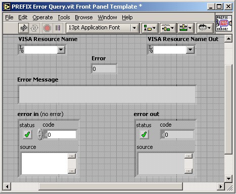
Figure 11: Front Panel of the Error Query VI
Low level API VIs do not call the Error Query VI. Many low-level API VIs are designed primarily to improve performance or to provide more control over instrument operations. For example, an oscilloscope instrument driver might implement a Read Waveform VI to return channel-based waveform data. To give advanced users more control, you should implement Initiate and Fetch VIs. The low-level Initiate and Fetch VIs give users more control over when the operations occur, so these low-level VIs do not call the Error Query VI.
Some instruments have an error queue, which stores errors and events as they are detected. This queue is first in, first out (FIFO), with a minimum length of two messages. In the event of overflows, the instrument retains the most recent errors/events, and replaces the least recent error/event with a queue overflow message. In your instrument driver, use this queue to detect and report instrument errors by querying the instrument after commands are sent. By issuing the :SYST:ERR? command, SCPI instruments return one entry from the queue, which can be an error, an overflow warning, or the message 0, "No error". Some end users want to retrieve the entire error queue, so many instrument drivers also include an Error Query (Multiple) VI. This VI queries the instrument with the :SYST:ERR? command until the error queue is empty.
The code generated by the Instrument Driver Project Wizard includes the Error Query VI.
Instrument driver VIs typically do not perform range checking on input parameters. If a user passes an invalid value, the instrument should report an instrument-specific error. The Error Query VI detects this instrument error and reports the out-of-range condition to the user. Document range information in the VI and control help so the user does not encounter out-of-range errors.
Additional Style Guidelines
Users appreciate consistency among instrument drivers. Developing simple front panels and block diagrams with an easy-to-understand layout makes end users less intimidated about modifying the code. Some users might need to modify the code to optimize it for their special needs. Refer to the Instrument Driver Guidelines for more information about style guidelines.
Testing the Operation
Test your instrument driver as you develop it. Although most users will use the Context Help window to determine the inputs to the VIs, some end users might not use the Context Help window to determine the inputs to the VIs and might pass invalid data to the VIs. Therefore, test your VIs with invalid data, boundary conditions and ranges, and unusual combinations of inputs. If a subVI requires string or array information, wire an empty array or empty string to the VI input.
See Also:
LabVIEW Help: Documenting VIs
Conclusion
Defining the structure of the VIs is the most important step in the development of an instrument driver. Group related instrument controls into modular VIs, each of which performs a task the way you actually would use the instrument from its front panel. With this type of structure, each VI gives users exactly what they need to perform a particular instrument operation. Determining which controls belong on each VI is the greatest challenge in developing instrument drivers.
For the end user, the logical structure, documentation, and error reporting are the most important features of the instrument driver. Include appropriate comments in all description boxes and document your code with comments in the block diagrams. Build useful error reporting into your VIs using the techniques described in this document. Thoroughly test all your VIs to ensure that they work properly.
Instrument driver development is more than building and sending strings to instruments. Use the Instrument Driver Project Wizard and the thousands of instrument drivers available on NI Instrument Driver Network (ni.com/idnet). Templates contain VIs common to most instruments and demonstrate the desired style and structure of instrument driver VIs. Use existing instrument drivers to help guide you through creating your own instrument driver. Follow the internal design structure and keep in mind the categories of API VIs as you build your VIs. Use the Instrument Driver Guidelines throughout your driver development process to ensure you create high quality instrument drivers. These tools help you design instrument drivers that are acceptable to a wide range of users.