Calculating Absolute Accuracy or System Accuracy
Overview
Contents
- Introduction
- Step 1: Identify Variables Affecting the Calculated Accuracy
- Step 2: Calculate the Absolute Accuracy for each Component
- Step 3: Calculate the System Accuracy and System Accuracy RTI
- Additional Information and Example Calculations
- Additional Resources
Introduction
First, you should understand that while related, code width and bits of resolution alone do not define the accuracy of your device or module.
This solution explains how to calculate the overall system accuracy by first determining the accuracy of each of the system components. The steps involved in calculating the system accuracy of measurement are:
- Determine your accuracy and environment parameters.
- Calculate Absolute Accuracy for each system component.
- Use the Absolute Accuracy values to calculate the System Accuracy and System Accuracy Relative to Input (RTI).
An example of the calculations are shown below in the additional information section.
Step 1: Identify Variables Affecting the Calculated Accuracy
First, determine how each component is connected to the system and identify all pertinent variables that will affect the calculated accuracy.
For this example, we'll assume an SCXI-1125 isolation module is cascaded using the SCXI-1352 cable to an SCXI-1141 filter module. This filter module is then connected to an NI 6052E DAQ device.
SCXI 1125 » SCXI 1141 » NI 6052E
Assume the following:
- Single Point Reading (no averaging)
- Ambient Temperature = 25°C
- SCXI-1125 Filter = 10 KHz
- SCXI-1125 Input Range = +/- 10 V
- SCXI-1141 Input Range = +/- 5 V
- NI 6052E Input Range = +/- 5 V
- "Typical" vs. "Max" % Reading = "Typical"
- Time Since Last Calibration = Less Than 1 Year
Step 2: Calculate the Absolute Accuracy for each Component
Next, calculate the Absolute Accuracy for each component.
For any individual device with gain (either an amplifier or attenuator), for a specified nominal range, NI provides an absolute accuracy specification in millivolts. Depending upon the presentation of different errors, there are three different equations to use to calculate the accuracy. All equations are listed below:
Equation 1:
Absolute Accuracy =± [(VoltageReading x GainError) + (VoltageRange x OffsetError) + NoiseUncertainty]
Where:
- GainError = ResidualGainError + (GainTempco x TempChangeFromLastInternalCal) + (ReferenceTempco x TempChangeFromLastInternalCal)
- OffsetError = Residual OffsetError + (OffsetTempco x TempChangeFromLastInternalCal) + INLError
- NoiseUncertainty* = (RandomNoise x 3) ÷ (√100)
*for a coverage factor of 3 σ and averaging 100 points
You can obtain the parameter values in the above equation by looking at the specifications found in each component's manual, specifications or datasheet.
Equation 2:
Absolute Accuracy =± [(InputVoltage x %ofReading) + (VoltageRange x Offset) + SystemNoise +TemperatureDrift]
Where:
- Input Voltage is the voltage range the device is configured for. For example, for +- 10V, Input Voltage = 1
- %ofReading is a raw % accuracy based on the input gain. This accounts for gain error
- Offset is the maximum offset error. Many times, this offset can be in ppm instead of % so in order to change this into %, use this conversion: 1% = 10,000 ppm
- SystemNoise is the error introduced to the measurement by the device itself. This will often depend on filter settings or whether a single sample is taken as opposed to multiple samples being averaged
- TemperatureDrift** =± [(InputVoltage x %ofReading/ °C) + (%Offset/ ° C)]*
**This accounts for errors introduced by ambient temperature variation. See notes in additional information section.
You can obtain the parameter values in the above equation by looking at the information found in each component's specifications, manual or datasheet.
Equation 3:
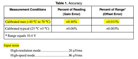
C Series Modules provide concise specifications for users to determine their accuracy throughout the entire operating temperature range (Calibrated Maximum -40 to 70). This accuracy entry accounts for temperature variations, worst case component tolerances, thermal hysteresis, etc.
Absolute Accuracy = ± [(InputReading x GainError) + (Range x OffsetError) + InputNoise]
Where:
- Input Reading- is the value that the user is trying to measure
- Gain Error- a raw % accuracy based on the input gain
- Range- the reading span that the device is configured for. For example for 0 to 10V, Range= 10
- OffsetError- the maximum offset error. In the datasheet it might be specified in ppm instead of %, for the conversion to percentage use 1%= 10,000ppm.
- InputNoise- is the error introduced to a measurement by the device itself. See notes in additional information section. See the image below for an example of what values to use.
All of the above specifications can be found in a datasheet or specifications of a component.
Step 3: Calculate the System Accuracy and System Accuracy RTI
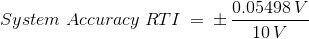
Finally, we will use the Absolute Accuracy from each component to calculate the System Accuracy and System Accuracy Relative to Input (RTI). Like the Pythagorean Theorem, the System Accuracy is equal to the square root of the sum of the squares of each component's Absolute Accuracy.

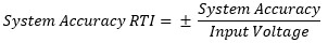
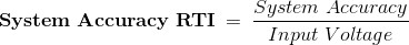
The System Accuracy Relative To Input (RTI) is calculated as follows:
Additional Information and Example Calculations
- An application, DC Accuracy Calculator, is attached in the Downloads section in order to calculate the accuracy of most C Series Modules.
- Temperature effects are already accounted for in the specification values unless your ambient temperature is outside of the 15°C to 35°C range. For instance, if the ambient temperature of your measurement system is at 45°C, you must account for 10°C of temperature difference. In this case, since the temperature is assumed to be 25°C in our example used for the exaplanation, we don't have to add in anything for Temperature Drift.
- Input Noise error will often depend on filter settings or whether a single sample is taken as opposed to multiple samples being averaged. When an average is taken, the effect of the input noise can be neglected. When no average is taken, the input noise can be converted into the appropriate units (voltage, current, etc.) by multiplying the Unit (rms) by a factor of 3. A multiplication by a factor of 3 assumes a Gaussian distribution that yields 99.73% confidence that the noise will be captured in this range. The noise is assumed to be Gaussian unless otherwise specified.
- Please note that terminal blocks or connector blocks are not considered gain stages unless they have attenuation circuitry. Modules or DAQ devices that do not have amplifiers are also not considered gain stages.
System Accuracy Example Calculations for the above referenced setup:
Here are the absolute accuracy calculations for each component of our system:
Absolute Accuracy of the SCXI-1125
Absolute Accuracy = ± [(InputVoltage x %OfReading) + Offset + SystemNoise + TemperatureDrift]
Absolute Accuracy = ± [(10 V x 0.002478) + 0.01 V + 0.0191 V + N/A] = ± 54.88mV
Absolute Accuracy of the SCXI-1141
Absolute Accuracy = ± [(InputVoltage x %OfReading) + Offset + SystemNoise + TemperatureDrift]
Absolute Accuracy = ± [(5 V x 0.0002) + 0.0006 V + 0.00142 V + N/A] = ± 3.02mV
Absolute Accuracy of the PCI-6052E
Absolute Accuracy = ± [(InputVoltage x %OfReading) + Offset + SystemNoise + TemperatureDrift]
Absolute Accuracy = ± [(5 V x 0.000071) + 0.000476 V + 0.000491 V + N/A] =± 1.322mV
System Accuracy


System Accuracy RTI

Additional Resources
- Calculate Absolute Accuracy of Dynamic Signal Acquisition Devices
- Calculating Accuracy for DMMs
- How Do I Determine the DC Accuracy of a NI Digitizer/Oscilloscope for a Given Input Value?
- Specifications Explained: NI Multifunction I/O (MIO) DAQ
- Specifications Explained: C Series Modules
- Specifications Explained: NI Oscilloscopes and Digitizers
