Choosing the Right Camera Bus
Contents
Introduction
Machine vision acquisition architectures come in many different forms, but they all have the same end goal: to transfer image data from a physical sensor into a processing unit that can analyze the image and take an action. This goal is the same for PC-based machine vision systems, embedded compact vision systems, and smart cameras.
Of these architectures, PC-based machine vision systems are the most popular because they provide the best performance and the most flexibility for the price. With that said, all physical architectures have the same starting point and ending point. You have a camera on one end and a processing unit on the other.
This white paper explores the strengths and weaknesses of the five major camera buses—Camera Link, USB 2.0, USB3 Vision, IEEE 1394, and GigE Vision—and describes the trade-offs you may need to make when deciding which camera bus is right for your application.
This white paper compares the five camera buses over the following seven categories on a relative scale:
- Throughput—The rate at which image data can be transferred over the bus.
- Effective cost—The overall component price of a system, including the camera, cables, frame grabbers, and software.
- Cable length—The maximum possible distance between the camera and the PC without repeaters.
- Standardized interface—A measure of ease of use and future scalability. Plug-and-play interfaces make some camera buses easier to use and allow for future system upgrades without significant rework.
- Power over cable—The ability of the camera bus to provide power to the camera over the same cable.
- CPU usage—The amount of CPU available to process images during image acquisition.
- I/O synchronization—The ease at which triggering and overall system communication is addressed and handled within the camera bus.
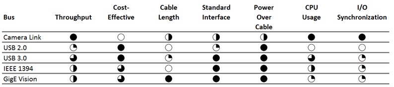
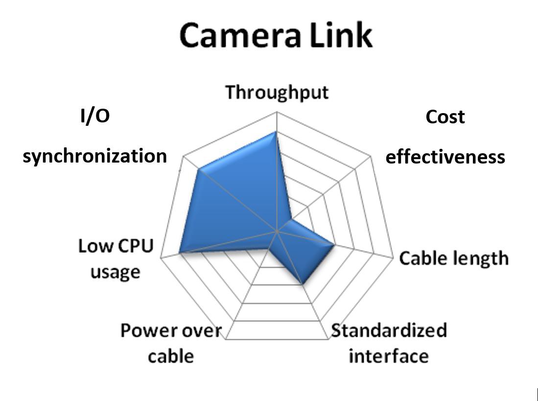
In this white paper, each camera bus receives a relative score for each of the seven categories above. A fully shaded circle is the highest score and an empty circle is the lowest. Not every application has a dominant bus, so the relative scores are represented in a “spider graph.” With these graphs, you can rank the camera buses yourself depending on which category is most important to you.
A summary of the relative rankings for each bus is shown in the table below. A detailed discussion for each bus is included in the following sections.
Camera Link
The cost of custom cables and the broad range of digital transmission formats were the driving force behind the development of the Automated Imaging Association (AIA) standard for high-speed transmission of digital video. The AIA standard is known as Camera Link, which defines the cable, connector, and signal functionality between the camera and the frame grabber. Any camera that complies with the Camera Link specification should work with any frame grabber that is also Camera Link-compliant.
Throughput: Camera Link, a high-speed serial digital bus designed specifically for machine vision cameras, offers the highest throughput of any camera bus. Camera Link provides a three-tiered bandwidth structure (base, medium, and full) to address a variety of applications. Base-configuration cameras acquire at up to 255 MB/s (3 bytes × 85 MHz), though most cameras use roughly 100 MB/s or less (1 or 2 bytes × 50 MHz or less). A typical base-configuration camera might acquire 1 Mpixel images at 50 frames/s or more. Medium- and full-configuration cameras acquire at up to 510 MB/s and 680 MB/s, respectively. A typical full-configuration camera can acquire 1,280 × 1,024 images at 500 frames/s, or larger 4 Mpixel images at more than 100 frames/s. Score: 5
Cost-effectiveness: Because Camera Link is designed for medium- to high-performance image acquisition, the cameras are generally more expensive than lower performance cameras. Also, Camera Link requires a frame grabber that can handle the high data rates described above. These cameras are more expensive than USB, IEEE 1394, or Gigabit Ethernet adapters. Score: 1
Cable length: The Camera Link standard replaces expensive, custom cables with a single, low-cost standard cable with fewer wires. Special components on the camera are used to serialize 28 parallel TTL signals into four high-speed differential pairs, which are transmitted across the cable. A similar component is used on the frame grabber to deserialize the data stream into parallel TTL signals. This reduces cable size and cost and increases noise immunity and maximum cable length.
The Camera Link specification defines a maximum cable length of 10 m. Camera Link uses a standardized cable that is relatively inexpensive and works with any Camera Link-compliant camera and acquisition device. Base-configuration cameras require only one cable. Medium- and full-configuration cameras require two cables. Score: 3

Standardized interface: The Camera Link specification defines a standard cable, connector, signal format, and serial communication API for configuring cameras. However, unlike IEEE 1394 and GigE Vision, the communication between the camera and PC is not defined by the standard. This means that every Camera Link camera requires a special camera configuration file to explain to the software how to acquire images from the camera, how to communicate with the camera, and which features can be modified. You can compare cameras and download camera files at ni.com/cameras. Score: 3
Power over cable: Camera Link offers an option known as Power over Camera Link (PoCL) for providing power to cameras over a cable. Several Camera Link-compliant NI frame grabbers work with this feature. Score: 3
CPU usage: Camera Link cameras require the use of frame grabbers, which transfer the image data to memory using DMA channels that do not burden the computer’s CPU. Because of this, Camera Link image acquisition uses very little of the system CPU. Score: 5
I/O synchronization: Although serial signals are defined on the cable pinout, the specific serial commands for setting exposure, gain, and offset, for example, are not defined by the specification. The frame grabber driver software must be configured to accommodate a particular camera’s serial commands. Control signals are also provided on the Camera Link cable for triggering and timing, but many manufacturers offer separate connectors for advanced triggering capabilities. Although the limited scope of the Camera Link specification does not provide plug-and-play compatibility, it gives camera and frame grabber companies an opportunity to differentiate their products by adding features or enhancing functionality. Overall, Camera Link offers the most I/O flexibility and capability. Because of their more demanding synchronization requirements, most linescan cameras use Camera Link. Score: 5
USB 2.0
Although USB was originally developed for the consumer market, it has also found a niche in the industrial market. Though USB 1.1 did not have sufficient bandwidth for anything more than a basic web camera, USB 2.0 has sufficient bandwidth for streaming video. USB 2.0 typically targets machine vision applications with relatively low performance requirements and low-cost cameras.
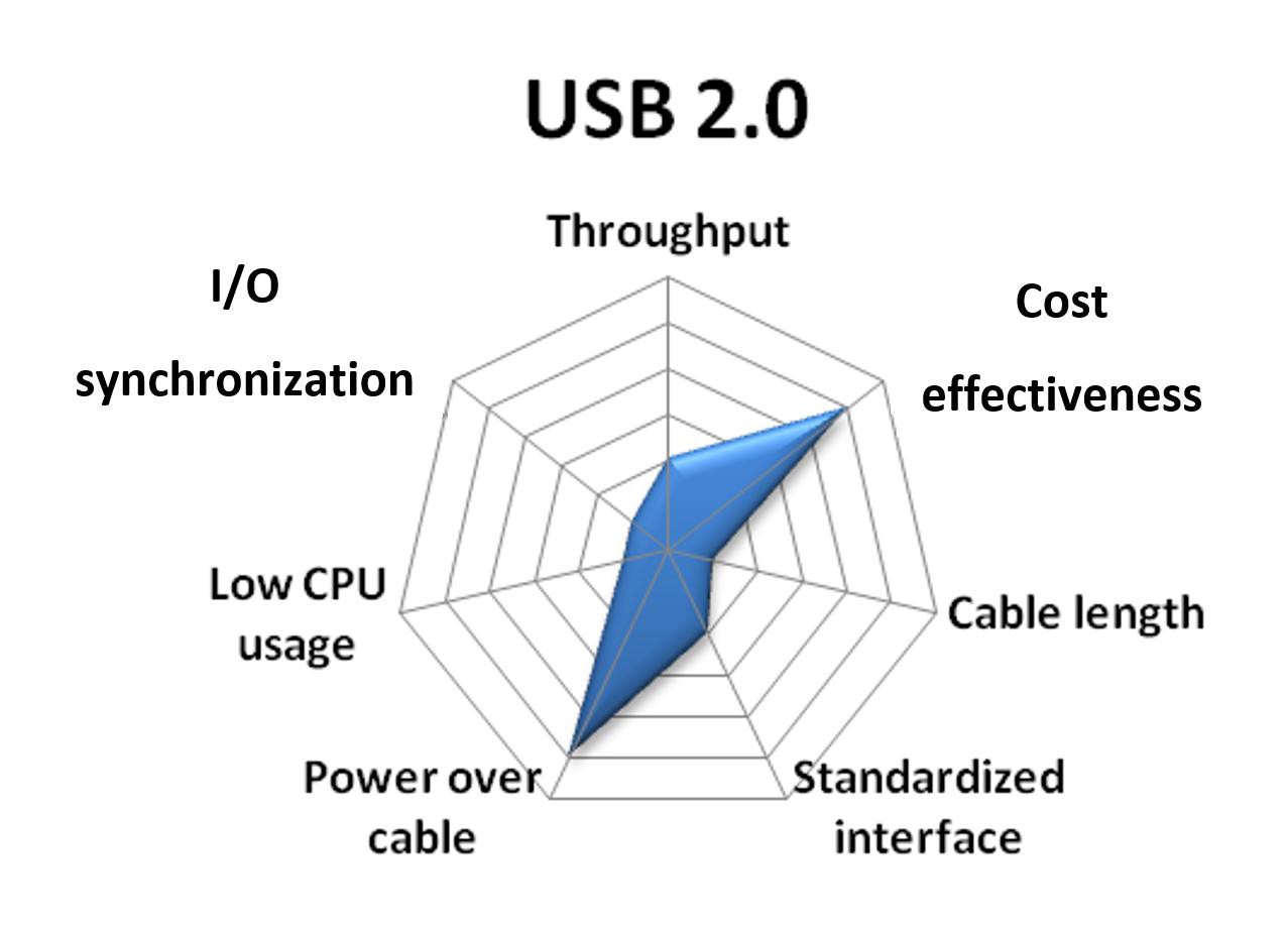
Throughput: USB 1.1 provided only 1.1 MB/s of data throughput. However, with the introduction and adoption of version 2.0, which provides bandwidths of up to 60 MB/s, USB became a viable bus for vision. The 60 MB/s is on par with IEEE 1394a. Score: 2
Cost-effectiveness: USB cameras are generally low-cost, especially if you do not need industrial features like triggering or extended temperature ranges. Also, they plug directly into any standard USB port, so no frame grabber is required. Because of this, USB is the least expensive camera bus and is widely used in academic labs and other cost-sensitive areas. Score: 5
Cable length: Cable lengths for USB are generally less than 5 m without a repeater, similar to IEEE 1394. With a repeater or a hub, you could reach lengths up to 30 m. Score: 1
Standardized interface: While several USB 2.0 ports are available on every PC built today, it is still the least standardized and least popular camera bus considered here. The one obstruction to the widespread adoption of USB for vision applications is the lack of a hardware specification for video acquisition devices. Each vendor has to implement its own hardware and software design, which means that a special driver must be written to connect each USB camera to each different software package. As a result, IEEE 1394 is much more prominent in vision applications. Score: 2
Power over cable: USB also provides power over the same cable, which eliminates the need for a separate power cable. Score: 5
CPU usage: Most image acquisition drivers for USB 2.0 use utilities like DirectShow to acquire images into the PC. While these tools work well, they are a burden on the CPU. As a result, USB 2.0 image acquisition can be processor-intensive. Score: 1
I/O synchronization: Utilities like DirectShow also do not provide any type of interface for triggering or communication. Because of this, without a special driver, it is very difficult to synchronize USB cameras with each other or the rest of a system. Score: 1
USB 3.0
The USB 3.0 standard, also known as SuperSpeed USB, is the second major revision of the USB standard for computer connectivity. USB 3.0 builds upon USB 2.0 to provide a higher throughput and can provide 4.5 Watts of power to peripheral devices. The USB3 Vision standard for cameras is built upon the USB 3.0 specification, and is built off existing standards such as the GigE Vision and standard for Gigabit Ethernet devices.
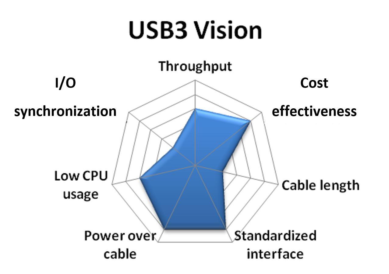
Throughput: While USB 2.0 provides a throughput of 60 MB/s, USB 3.0 provides a throughput of 400 MB/s. This is faster than Camera Link Base configurations at 255 MB/s and approaches that of a medium-configuration Camera Link camera at 510 MB/s. Score: 4
Cost-effectiveness: USB cameras are generally low-cost, especially if you do not need industrial features like triggering or extended temperature ranges. Also, they plug directly into any standard USB port, so no frame grabber is required. Because of this, USB is the least expensive camera bus and is widely used in academic labs and other cost-sensitive areas. Score: 5
Cable length: Cable lengths for USB 3.0 are generally less than 5 m without a repeater, similar to IEEE 1394 and USB 2.0. Active cables for USB 3.0 devices are in development, and will allow cable lengths much greater than 5 m. Score: 2
Standardized interface: Though USB 2.0 standardization has been relatively poor, USB3 Vision is based on existing standards such as GigE Vision and the standard for Gigabit Ethernet devices, so cameras will have an XML file that defines supported camera features. USB3 Vision will use the GenICam programming interface to allow access to common and vendor-specific features. This will ensure interoperability regardless of the CPU, OS, and software package. Score: 5
Power over cable: USB 3.0 also provides power over the same cable, up to 4.5 W, which eliminates the need for a separate power cable. Score: 5
CPU usage: USB3 Vision permits zero-copy image transfers of image data directly into host memory with no CPU usage. Score: 4
I/O synchronization: Similar to 1394 and GigE Vision, I/O synchronization is inherently more challenging without a frame grabber to broker communication signals and triggers. Some USB 3.0 cameras provide direct trigger input and output lines. Also, a few plug-in boards offer isolated digital I/O and triggering, which greatly simplify system synchronization. Score: 2
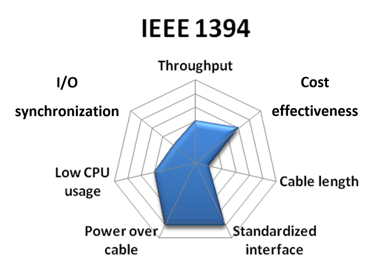
IEEE 1394

The initial IEEE 1394 specification was released in December 1995. Unlike USB, IEEE 1394 was never intended for basic computer peripherals—it was designed for imaging equipment. The initial speed of IEEE 1394a was 100 Mb/s compared with the 1.5 Mb/s of USB 1.1. This higher bandwidth is better suited for devices such as cameras and hard drives. Because of the initial bandwidth advantages of IEEE 1394, it is now the widespread standard for vision systems today, even though USB 2.0 has caught up in terms of throughput.
Throughput: The IIDC specification for IEEE 1394 cameras (explained below) defines several standard frame rates that range from 1,875 frames/s to 240 frames/s as well as standard resolutions from 160 × 120 to 1,600 × 1,200. The specification also provides for a scalable image format, known as Format 7, which allows for almost any arbitrary resolution and frame rate. Format 7 images are limited only by the available bandwidth on the IEEE 1394 bus and the camera manufacturer’s implementation decisions. For many cameras, frame rate scales inversely with image resolution along a roughly constant curve. The IEEE 1394a specification provides a maximum data rate of 400 Mb/s, which is enough for a 640 × 480 8-bit monochrome acquisition at 100 frames/s. The IEEE 1394b specification doubles the available bandwidth to 800 Mb/s and the maximum frame rate at 640 × 480 to 200 frames/s. Score: 3
Cost-effectiveness: IEEE 1394 cameras, which offer digital image quality, extended features, and ease of use, are relatively cost-effective. Furthermore, they do not require special frame grabbers to acquire images into a PC. Add to this the low cost of cables, and IEEE 1394 is a very cost-effective camera bus for vision. Score: 4
Cable length: IEEE 1394 cameras use standard, low-cost cables that are widely available. Point-to-point connections for IEEE 1394a are limited to less than 5 m, with longer distances possible using hubs or repeaters. IEEE 1394b cameras support longer single runs up to 100 m over fiber or CAT 5 cable. Solutions are also available outside the specification that allow IEEE 1394a to be used across much longer distances over fiber-optic cable. Score: 1
Standardized interface: Several years ago, the 1394 Trade Association formed a working group to define an industrial camera specification. The resulting 1394 Trade Association Industrial and Instrumentation specification for Digital Cameras (IIDC) defines a vendor-agnostic hardware register map that allows basic query and control of the camera. Several video and external triggering modes are supported. The vendor-agnostic nature of the specification promotes interoperability between different hardware and software. This hardware, software, and cabling standard makes IEEE 1394 the easiest camera bus to use and maintain. Score: 5
Power over cable: IEEE 1394 has power on the cable. Most cameras can draw power off the IEEE 1394 bus without the need for an external power source. High-power devices still require an external power source. Score: 5
CPU usage: IEEE 1394 does not require a frame grabber, which means it relies on the CPU to transfer images to system memory. CPU rates differ among software providers, but, in general, the overall usage is higher than that of frame grabbers. Score: 3
I/O synchronization: Just like USB and GigE Vision, I/O synchronization is inherently more challenging without a frame grabber to broker communication signals and triggers. With that said, many IEEE 1394 cameras provide direct trigger input and output lines. Also, a few IEEE 1394 plug-in boards offer isolated digital I/O and triggering, which greatly simplify system synchronization. Score: 2
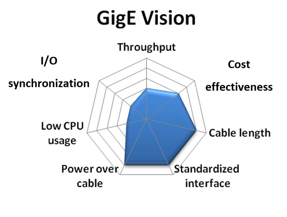
GigE Vision
Gigabit Ethernet is a new camera bus technology for machine vision systems. With relatively high bandwidth, long cable lengths, and wide usage in the consumer and industrial applications, Gigabit Ethernet shows promise for security and long-distance vision applications.
Unlike USB and IEEE 1394, Ethernet was not originally intended to connect peripherals. Ethernet does not offer plug-and-play notification. Device discovery requires additional protocols or user intervention. These shortcomings are addressed in the new GigE Vision standard from the Automated Imaging Association (explained below).
Throughput: The theoretical maximum bandwidth of Gigabit Ethernet is 125 MB/s. With hardware limitations and software overhead, the practical maximum bandwidth is closer to 100 MB/s. This bandwidth is the same as IEEE 1394b and is second only to Camera Link. Score: 3
Cost-effectiveness: The overall system cost of GigE Vision is very similar to IEEE 1394. The cameras may be slightly more expensive, but the cabling is cheaper. Neither requires a frame grabber. Score: 4
Cable length: Cable length is truly where GigE Vision excels. With cable lengths reaching 100 m, GigE Vision is the first camera bus to rival the now outdated analog camera in terms of cable length. This characteristic has helped GigE Vision replace analog in security and monitoring applications. Score: 5
Standardized interface: Recently, the Automated Imaging Association along with several member companies defined an in-depth industrial camera standard built on top of Gigabit Ethernet called GigE Vision. The GigE Vision standard overcomes some of the shortcomings of Gigabit Ethernet by providing plug-and-play behavior, device discovery, error handling, and secure image transfer. The GigE Vision standard offers a level of standardization that is similar to IEEE 1394's in terms of ease of use and hardware scalability. Score: 5
Power over cable: Power over Ethernet (POE) is available on many GigE cameras. However, most Ethernet cards do not supply sufficient power, so a powered switch, hub, or a POE injector must be used. Score: 5
CPU usage: Different software implementations of the GigE Vision standard yield very different CPU loads. In general, two types of drivers acquire images from GigE Vision cameras: filtered and optimized. Filtered drivers separate incoming image data packets from other traffic on the network at a high level. They are easier to create and use, but they heavily use the system CPU. Optimized drivers written specifically for a dedicated network interface card (NIC) work at a much lower level. For instance, by writing an optimized driver for an Intel NIC, packets containing image data can be separated at the NIC instead of the CPU. These optimized drivers use very little of the CPU and are essential for processor-intensive image processing applications. Score: 2
I/O synchronization: Because GigE Vision applications often use the long distances between the PC and the camera, triggering and communication are a little more challenging than with IEEE 1394. Usually with IEEE 1394, a proximity sensor is connected to the PC that then triggers the camera with a known pulse. However, with Ethernet distances up to 100 m, using the PC to condition a trigger signal between a proximity sensor and the GigE Vision camera is more difficult. Score: 2
Conclusion
In general, low- to medium-bandwidth applications are often equally well served by multiple camera buses. IEEE 1394a cameras accommodate applications that require bandwidth of up to about 40 MB/s. GigE Vision and IEEE 1394b cameras currently fill the gap between 40 MB/s and about 100 MB/s. Requirements above 100 MB/s but lower than 400 MB/s can be met by Camera Link base-configuration or USB3 Vision cameras. For applications beyond 400 MB/s, medium- and full-configuration Camera Link becomes a compelling—and sometimes the only—choice.
The goal of this white paper was not to illustrate that one camera bus is better than another. Instead it shows the many suitable camera buses available today that you can choose from for your application.