Grounding Considerations for Improved Measurements
Overview
Learn how grounding can determine how a measurement system should be connected for the most accurate measurements. Article topics include grounded signal sources, floating signal sources, differential measurements, single-ended measurements, and the proper signal and measurement configuration. This tutorial is part of the Instrument Fundamentals series.
Contents
- Grounding and Measurements
- Signal Sources
- Measurement Systems
- Signal Source–Measurement System Configurations
- Summary
- Next Steps
Grounding and Measurements
Measurement systems can have the ability to use different grounding configurations because signal sources can also have different grounding configurations. This capability is essential to ensure the most accurate measurement; however, this flexibility adds some difficulty when choosing the grounding configuration of the measurement system.
Figure 1 shows a block diagram of components used to make a measurement. On the right a measurement system is comprised of an instrument and signal conditioning. It should be noted that signal conditioning can be integrated in your instrument or it could be external to the instrument. On the left we have the signal source, which could be a single transducer producing a voltage from a physical phenomena or it could be a device under test. In this article we will talk about grounding on the signal source, grounding on the measurement system, and finally how to choose a measurement system configuration to ensure minimal measurement noise and error.
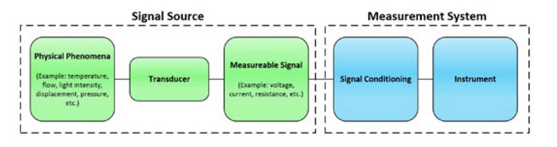
Figure 1: A signal source is fed into a measurement system that comprises an instrument and signal conditioning.
Signal Sources
There are two main categories of signal sources that should be considered for this grounding discussion; they are shown in schematic form in Figure 2.
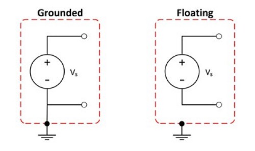
Figure 2: It is important to know if your signal is grounded or floating.
Grounded or Ground-Referenced Signal Sources
A grounded signal source is when a voltage signal is referenced to a system ground, such as earth or building ground. This is represented by the schematic on the left of Figure 2 above because the voltage signal has a direct electrical path to the system ground. The most common examples of grounded sources are devices that plug into the building ground through three pronged wall outlets such as signal generators and power supplies. It is important to know that the grounds of two independently grounded signal sources are typically not at the same potential. The difference in ground potential between two systems connected to the same building ground can be 10 mV, 200 mV, or more.
Ungrounded or Floating Signal Sources
An ungrounded or floating signal source is one in which the voltage signal is not referenced to a system ground, such as earth or building ground. This is represented on the right in Figure 2. Note that neither the positive nor negative terminal has a direct electrical path to a ground. Some common floating signal sources are batteries, thermocouples, and transformers.
Measurement Systems
You can configure instruments in one of three modes: differential (DIFF), referenced singleended (RSE), or nonreferenced single-ended (NRSE).
Differential Measurement Systems
A differential instrument requires two inputs where neither input to the instrumentation amplifier is referenced to a system ground. This is illustrated in Figure 3, where CH0+ and CH0- are wired into the positive and negative terminals of the instrumentation amplifier respectively, but they are not connected to the measurement system ground (AI GND).
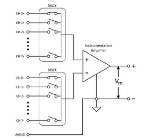
Figure 3: An ideal differential acquisition system responds to only the voltage difference between its two terminals.
An ideal differential acquisition system responds to only the voltage difference between its two terminals, the positive (+) and negative (-) inputs. The differential voltage across the circuit pair is the desired signal, yet an unwanted signal that is common to both sides of a differential circuit pair can exist. This voltage is known as common-mode voltage. An ideal differential measurement system completely rejects, instead of measures, the common-mode voltage for more accurate measurements. Practical devices, however, have limitations described by specifications such as common-mode voltage range and common-mode rejection ratio (CMRR).
The common-mode voltage range is the maximum allowable voltage swing on each input with respect to the instrument ground. To violate this constraint results in not only measurement error but also possible damage to instrument components. Here is the formula to calculate the common-mode voltage:
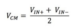
Equation 1: Common Mode Voltage Calculation
Where:
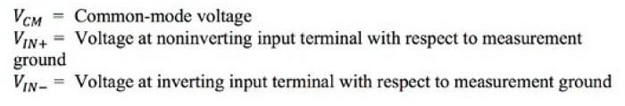
An example of violating the common-mode voltage range specification would be to attempt a differential measurement with one lead at 110 V and the other lead at 100 V. Although the differential measurement is 10 V, which may be within specification for the device, the common-mode voltage would be 105 V and this may not be within the specification of the instrument.
CMRR describes the ability of a measurement system to reject common-mode voltages. Amplifiers with higher CMRRs are more effective at rejecting common-mode voltages and are, therefore, more desirable for accurate measurements. The CMRR can be described as a ratio of the differential gain over the common-mode gain, seen in Equation 2. CMRR can also be described in dB as shown in Equation 3.
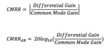
Equation 3: CMRR Expressed in dB
For example, if the instrument has a CMRR of 100,000:1 (or 100 dB) and the common-mode voltage is 5 V, you can distinguish voltage differences greater than 50 μV on the differential leads. Common-mode rejection is critical because noise sources from the environment are present on both lines of the differential measurement. However, if the noise is present on both lines, it is cancelled out by the differential measurement. For this reason, differential configurations lead to more accurate measurements in comparison to single-ended measurements, but differential measurements require double the channel count compared to single-ended measurements.
Single-Ended Measurement Systems
Single-ended configurations are commonly the default configuration for instruments. They differ from differential configurations because only one analog input channel is required for the measurement. All channels on the instrument use the negative input to the instrumentation amplifier as the common reference, which can be seen in Figure 4. Because single-ended configurations use only one input, they can take twice the number of measurements compared to a differential configuration system with the same number of physical channels. On the other hand, this leaves single-ended measurements susceptible to ground loops, which can decrease the accuracy of the measurements.
Below are two different types of single-ended measurement systems:
- Ground RSE (GRSE) or RSE systems have the common reference channel connected to the instrument ground. In the example RSE system shown in Figure 4, the instrument ground channel is labeled AI GND.
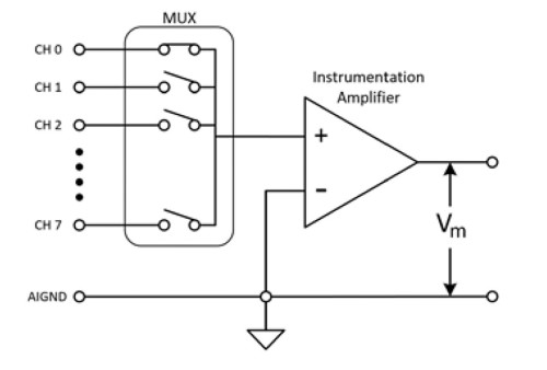
Figure 4: A GRSE or RSE system’s common reference channel is connected to the instrument ground.
- NRSE instruments reference a common point; however, the common point is the voltage provided at the negative terminal of the instrumentation amplifier. In the NRSE example shown in Figure 5, the common reference is the AI SENSE line; therefore, the measured voltage is the potential difference between CH X and the voltage at the AI SENSE channel.
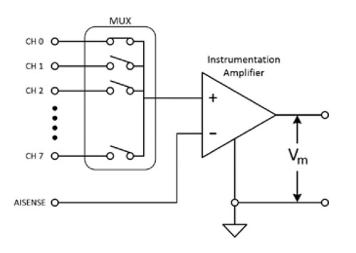
Figure 5: An NRSE instrument’s common point is the voltage provided at the negative terminal of the instrumentation amplifier.
Signal Source–Measurement System Configurations
After characterizing both the signal source grounding types and the instrument configurations, we will now discuss which combinations of signal sources and instrument configurations can yield the most accurate results.
Measuring Grounded Signal Sources
A grounded signal source is most accurately measured with a differential or NRSE instrument configuration because an additional ground is not introduced into the entire system. An additional ground added to the system can result in ground loops, which are common sources of noise in measurement applications.
Ground loops occur when two connected terminals in a circuit are at different ground potentials, causing current to flow between the two points. The ground of the signal source can be several volts above or below the ground of the instrument. This additional voltage can cause error in the measurement itself and the flowing current can also induce voltages on nearby wires causing additional measurement error. These errors can appear as scalar or periodic signals added to the measured signal. For example, if a ground loop is formed with a 60 Hz AC power line, the standard power line frequency in the United States and some other countries, the unwanted 60 Hz AC signal can appear as a periodic voltage error in the measurement.
To calculate the measured voltage, V_m, use Equation 4 below:
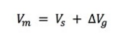
Equation 4: Measured Voltage With a Ground Loop Present
Where:
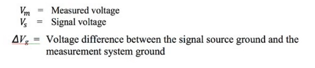
Using Equation 4 above mathematically gives you the measured voltage when a ground loop is present. If you continue to use the 60 Hz power line example, ΔV_g is a value that changes with time instead of a scalar offset. Therefore, the measured signal looks periodic instead of like a simple offset error for the measured voltage.
Figure 6 shows what a system with a ground loop looks like in schematic form. If you are measuring the voltage source V_s with an instrument using an RSE configuration, you can simplify the schematic on the left of the equation with the schematic on the right of the equation in Figure 6, which agrees with the calculations in Equation 4.
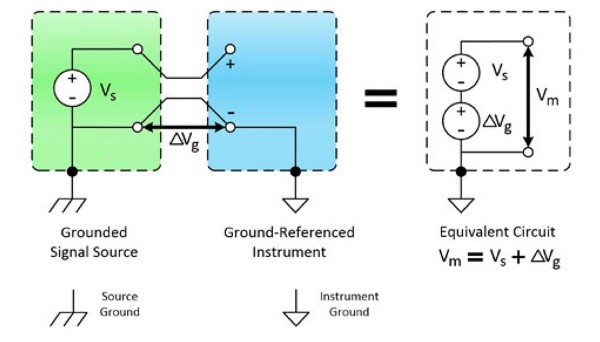
Figure 6: A grounded signal source measured with a ground-referenced system introduces ground loops and measurement error.
To avoid ground loops as shown in Figure 6, ensure only one ground reference exists in the signal source and the measurement system by using a differential or NRSE instrument configuration or by using isolated measurement hardware, which is discussed in the Isolation Types and Considerations when Taking a Measurement white paper of the Instrument Fundamentals Series.
Measuring Floating Signal Sources
You can measure floating signal sources with any of the measurement configurations discussed: differential, GRSE/RSE, or NRSE. Note that when using differential or NRSE measurement configurations with a floating source, you must include bias resistors from each lead, positive (+) and negative (-), to the instrument ground (see Figure 7).
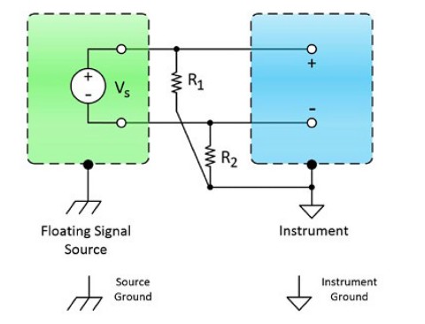
Figure 7: When measuring a floating signal source with a differential or NRSE instrument configuration, bias resistors are needed.
Bias resistors provide a DC path from the instrument amplifier inputs to the instrument amplifier ground. Bias resistors should have a high enough resistance to not load the signal source and to allow the signal source to float with respect to the instrument reference. However, the bias resistors should be small enough to keep the voltage within the range of the instrument. This typically results in bias resistors with a range of 10 kΩ to 100 kΩ to satisfy the conditions. You should always double-check the specifications guide of your device to ensure you use a bias resistor value that is within the suitable range.
If bias resistors are not used in a differential or NRSE configuration when measuring floating signal sources, the measured signals can be unstable or at positive or negative full-scale range of the instrument.
When a GRSE/RSE configuration is used to measure a floating signal source, bias resistors are not necessary. To get the best measurement results when using single-ended instrument configurations, the following is recommended:
- The input signals are equal to or greater than 1 V.
- Signal cabling is relatively short and travels through a noise-free environment (or is properly shielded).
- All input signals can share a common, stable, and known reference signal–generally a point in the system where the voltage is at 0 V.
For a summary of the recommended combinations of signal sources and instrument configurations, refer to Figure 8. Grounding and Measurements
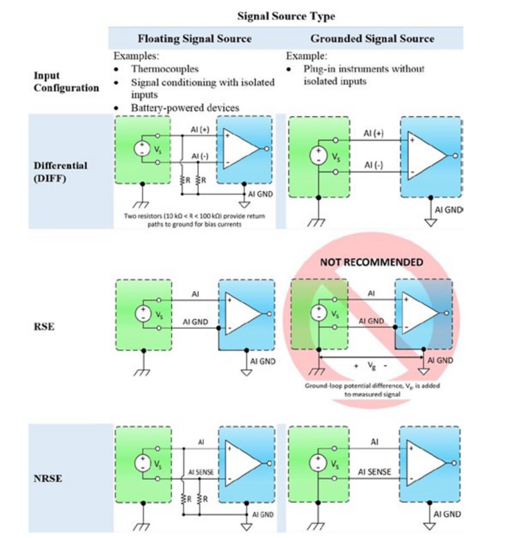
Figure 8: Instrument Configuration Versus Signal Source Type Summary.
Summary
- Measurement systems include an instrument and signal conditioning. Depending on the instrument, signal conditioning can be a part of the instrument or external.
- Two main categories of signal sources:
- Grounded signal source: Signal has a direct electrical path to ground.
- Floating signal source: Signal does not have a direct electrical path to ground.
- Instruments can have three main measurement configurations:
- Differential: A measurement that takes two input channels and is the most accurate configuration because it removes common-mode voltages.
- Ground referenced single-ended (GRSE) or referenced single-ended (RSE): A measurement that uses only one channel and the instrument ground; however, this single-ended measurement type is susceptible to noise.
- Nonreferenced single-ended (NRSE): A type of measurement that uses only one channel and a common reference point, which is not ground; however, this system is more susceptible to noise in comparison to differential measurements.
- Differential or NRSE instrument configurations are recommended to measure a grounded signal source.
- Differential, GRSE/RSE, or NRSE instrument configurations are recommended configurations to measure a floating signal source.
- Bias resistors must be used in differential or NRSE instrument configurations to measure a floating signal source.