Using the Counter Output Event Property in NI-DAQmx
Contents

Overview
A counter is used to increment a register value (count) based on the comparison of input signals and to generate output pulses based upon the register value. It has at least two inputs, the source and the gate and depending on the application may also use an output line as shown in Figure 1.
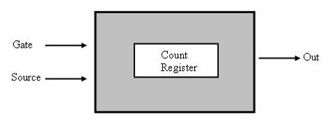
Figure 1. Counter Chip Components
Count Registers
A counter uses a count register to store the current count. The count increments or decrements when an edge is detected on the source input. National Instruments counter chips are equipped with both a software and a hardware register. The hardware register stores the current count as the signal are acquired while the software register keeps a copy of the hardware register to allow application query the register without interfering with the hardware counting operation.
Counter Size
The counter's size is the highest number a particular counter chip can count before it rolls over to zero. Counts are normally represented as binary bits on a count register with the total number of bits (N) representing the resolution of the counter. Thus the maximum number of count is given by
2^N - 1 where N is the number of bits
For example a counter with resolution of 24bit has a maximum count of 2^24 – 1= 16,777,215
Counter Terminal Count (TC)
Terminal count is hit when the count register rolls over to zero. When the counter hits the TC, the counter output can be programmed to either toggle between logic low and high or send a pulse on the output pin. The output signal generated can be used to alert a device or process.
Counter Output Event
When the terminal count is reached can be determined in hardware by using the Counter Output Event property in DAQmx. The Counter Output Event is an event that occurs when the counter reaches its terminal count. DAQmx allows you to select the signal’s output behavior and export the Counter Output Event to a specified terminal.
To configure the Counter Output Event use the DAQmx Export Signal Property Node. This is located in LabVIEW under Measurement I/O >>DAQmx-Data acquisition >> DAQmx Advanced Task Options >> DAQmx Export Signal as shown in Figure 2.
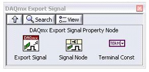
Figure 2. DAQmx Export Signal Sub-palette
With the counter output event, you can define the following properties;
- Counter Output Terminal
- Counter Output Behavior
- Counter Output Pulse Polarity
- Counter Output Toggle State
These properties are located under DAQmx Export Signal Property Node >> Events >> Counter Output Event as shown in Figure 3.
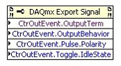
Figure 3. Counter output event properties
The Output Behavior property specifies the output behavior (pulse or toggle) of the Counter Output Event while the Output Terminal property specifies the terminal to which the signal will be routed.
You can cause the signal to generate a single pulse or to toggle states on the terminal count and further specify the polarity of the output pulse or the idle state if the line is set to toggle.
- For a pulsed line use the Pulse >> Polarity property.
- For a toggled line use the Toggle >> Idle State property.
Figure 4 shows a sample digital edge count operation with the Counter Output Event used to determine the terminal count and generate a pulse with active high polarity.
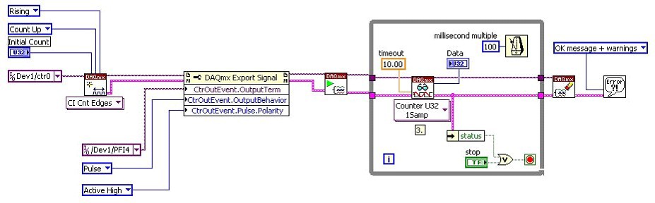
Figure 4. Simple Edge Counting with Terminal Count Output Event