NI-DAQmx Data Acquisition Triggering Techniques Using LabVIEW
Overview
Synchronization of the data acquisition (DAQ) process relative to an external event is an important criterion in many DAQ applications. For example, you may want to collect data after receiving a pulse signal from an encoder or when the temperature of a chamber exceeds a critical value. In such instances, the DAQ system must be set up to start the analog-to-digital (A/D) conversions as soon as the external event, or trigger occurs.
A triggered acquisition provides two key benefits to the user: It times the input signal relative to the trigger event so the user captures the signal only in the region of interest and thus conserves hardware bandwidth and memory.
Contents
- Trigger Types: Analog vs. Digital
- Acquisition Type: Posttrigger vs. Pretrigger
- Developing Triggered Applications with LabVIEW and NI-DAQmx
- Additional Resources
Trigger Types: Analog vs. Digital
NI-DAQmx supports both analog and digital triggers.
Analog Trigger
The level and slope of an analog signal triggers the acquisition (Figure 1). In such a system, analog trigger circuitry (ATC) on the DAQ hardware continuously monitors the analog signal to determine if it satisfies the trigger conditions. Once the trigger conditions are met, the ATC generates an internal trigger signal to initiate the acquisition.
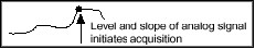
Figure 1: Analog Trigger Condition of Level and Slope
Digital Trigger
The rising or falling edge of a TTL signal initiates the data acquisition (Figure 2).
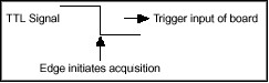
Figure 2: Digital Trigger
Acquisition Type: Posttrigger vs. Pretrigger
Triggered data acquisition applications can be classified in two ways: posttriggered and pretriggered.
Posttriggered Acquisition
In a posttriggered acquisition, the hardware starts the A/D conversions after the trigger is received (Figure 3). The trigger signal in this case is referred to as the start trigger.
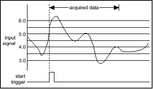
Figure 3: Posttriggered Acquisition
Pretriggered Acquisition
In a pretriggered acquisition, the hardware starts acquiring data before the trigger signal is received (Figure 4). With this type of acquisition, the user can view the signal before the trigger event. In such applications, the hardware initiates data acquisition with a software function and stores the data in a circular buffer in the PC memory. The buffer is large enough to ensure that the required number of pretrigger samples are stored. When the buffer is full, it simply wraps around and stores each subsequent sample over the oldest sample in memory. The primary responsibility of the trigger mechanism is to stop the acquisition so that the samples left in memory represent the “slice-in-time” the user wants. The trigger signal in this case is referred to as the reference trigger.
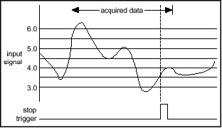
Figure 4: Pretriggered Acquisition
Developing Triggered Applications with LabVIEW and NI-DAQmx
This section serves as a guideline for developing triggered applications using the NI-DAQmx driver in LabVIEW. Alternatively, you could use the same design process to program a triggering application in a text-based programming environment. In this case, you would simply make function calls from the NI-DAQmx API.
NI-DAQmx applications typically consist of the four building blocks shown below (Figure 5).
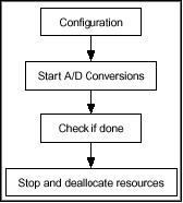
Figure 5: Flowchart for a Typical DAQmx Application
Trigger conditions for any application are specified in the configuration section by calling the appropriate NI-DAQmx functions or VIs in LabVIEW. The DAQmx Digital Trigger VI shown below can be used to configure a digital triggering task. You can use this VI to specify the source of the trigger and the desired edge to trigger on. In addition, more complicated triggering tasks can be implemented using the DAQmx Trigger Property Node.
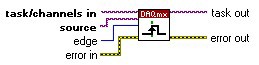
Figure 6: DAQmx Triggering VI
The rest of this document discusses how to implement various triggering types using LabVIEW and NI-DAQmx functions.
A. Posttriggered Acquisition with a Digital Start Trigger
In a posttriggered acquisition, the A/D conversions start after the DAQ hardware receives the trigger signal. The digital trigger is typically wired to the external trigger input of the I/O connector of the specified device.
The following code shows how to set up a posttriggered application using NI-DAQmx functions:
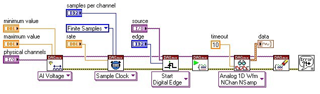
Figure 7: Posttriggered Acquisition with a Digital Trigger
In this example, the Analog Input task will wait until it sees the digital trigger. If the triggering edge is defined as Rising, then the analog input task will begin as soon as a rising edge occurs on the specified digital line.
The NI E and M Series multifunction I/O devices provide the added flexibility to choose from one of the several PFI lines on the board as the trigger input. The default trigger source is PFI0, but an alternate trigger source (e.g., another PFI line or RTSI line) can be selected by setting the Source of the DAQmx Trigger VI.
B. Pretriggered Acquisition on a Digital Reference Trigger
In a pretriggered acquisition, the A/D conversions are initiated with a software function call. NI-DAQmx stores the digitized data in computer memory in a circular buffering scheme, replacing the oldest points in the buffer with the new samples. Once the trigger signal is received, a specified number of points before and after the trigger are returned to the calling application (e.g., LabVIEW, C++, etc.) by the driver.
Figure 8 illustrates how to create a pretriggered application in LabVIEW by specifying the desired number of pretrigger samples in the DAQmx Reference Trigger VI. Note that setting the pretrigger samples to zero creates a posttriggered acquisition.
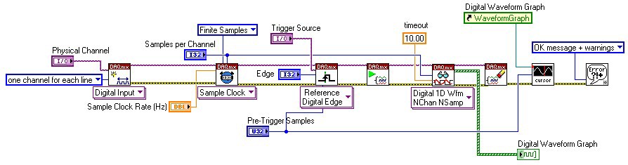
Figure 8: Pretriggered Acquisition with a Digital Reference Trigger
C. Pretriggered Acquisition with Start and Reference Triggers
You can also set up an acquisition that uses both a start and reference (stop) trigger. In this case, a digital or analog trigger starts the acquisition instead of a software function. Once the acquisition starts, a circular buffering scheme (similar to the previous case) is implemented until the reference trigger signal is received. The data returned consists of the specified number of pretrigger and posttrigger samples relative to the reference trigger signal (Figure 9).
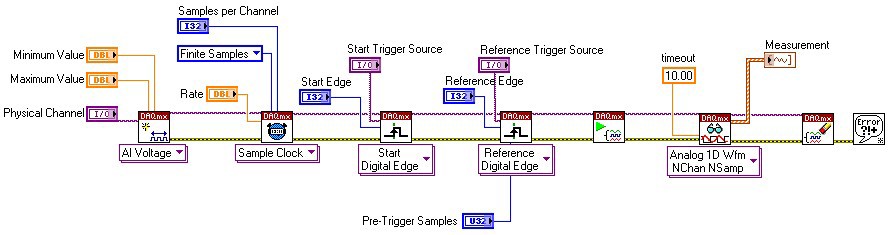
Figure 9: Acquisition with a Digital Start and Reference Trigger
D. Analog Hardware Triggering
For analog edge triggering, you configure the measurement device to look for a certain signal level and slope (either rising or falling). After the device identifies the trigger condition, the device performs the specified action associated with the trigger, such as starting the measurement or marking which sample was acquired when the trigger occurred. You connect analog trigger signals to any analog input channel or terminal capable of accepting analog signals.
In the following figure, the trigger is set to capture data for a rising edge signal when the signal reaches 3.2.
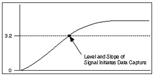
Figure 10: Analog Edge Triggering
Figure 11 illustrates how to specify the appropriate parameters in the DAQmx Analog Trigger VI to implement analog hardware triggering in LabVIEW.
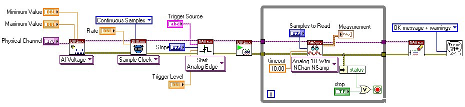
Figure 11: Analog Start Triggering in LabVIEW
E. Analog Triggering With Hysteresis
You can also specify hysteresis as a condition for analog triggering. Hysteresis adds a window above or below the trigger level and often is used to reduce false triggering due to noise or jitter in the signal. When using hysteresis with a rising slope, the trigger asserts when the signal starts below level (or threshold level) minus hysteresis and then crosses above level. The trigger deasserts when the signal crosses below level minus hysteresis.
For example, if you add a hysteresis of 1 to the previous example, which used a level of 3.2, the signal must start at or drop below 2.2 for triggering to occur. The trigger then asserts as the signal rises above 3.2 and deasserts when it falls below 2.2.
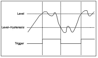
Figure 12: Hysteresis with Rising slope
When using hysteresis with a falling slope, the trigger asserts when the signal starts above level (or threshold level) plus hysteresis and then crosses below level. The trigger deasserts when the signal crosses above level plus hysteresis. If you instead trigger on a falling edge at 3.2 with a hysteresis of 1, the signal must start at or rise above 4.2 for triggering to occur. The trigger will then assert as the signal falls below 3.2 and deassert when it rises above 4.2.
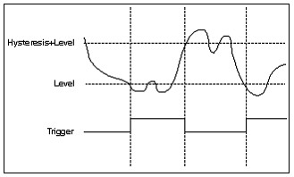
Figure 13: Hysteresis with Falling slope
Hysteresis is specified in LabVIEW by using the triggering property node. The following figure shows a section of code that creates an analog trigger with a hysteresis of one.
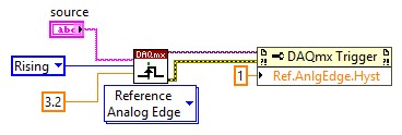
Figure 14: Level = 3.2, Slope = Rising, Hysteresis = 1.0
F. Pause Trigger
Some DAQ applications may require the user to implement a pause/resume feature where an external signal controls when the DAQ hardware performs the A/D conversions during an acquisition. NI DAQ boards support such a functionality using a feature known as “pause trigger” (NI-DAQmx). Here, the internal sample (scan) clock is gated by an external signal such that the sample (scan) clock pauses while the external signal is low and resumes when the signal goes high (or vice versa). Pause trigger (scan clock gating) can be classified into two types, digital or analog, depending on the nature of the gate signal. The following figure shows a typical implementation of a digital pause trigger in LabVIEW.
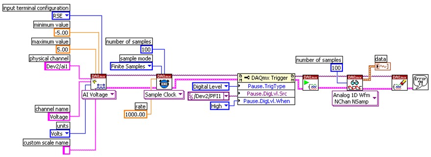
Figure 15: DAQmx Pause Trigger (Digital)
G. Digital Pause Trigger
In digital pause trigger, the gate signal for the sample clock is a TTL signal. Any PFI line can be used for as a gate signal on the DAQ card. The figure shown on the slide shows the timing diagram for high-level digital pause triggering. In the figure below each rising edge of the sample clock signal indicates the initiation of a scan:
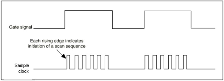
Figure 16: Digital Pause Trigger
H. Analog Pause Trigger
In analog pause trigger, the gate signal is an analog signal whose voltage level determines when the acquisition occurs. Only the devices that have analog trigger capability support this feature. The figure below illustrates the timing diagram for high level analog pause trigger where the A/D conversions occur only while the analog signal is above a critical voltage level.
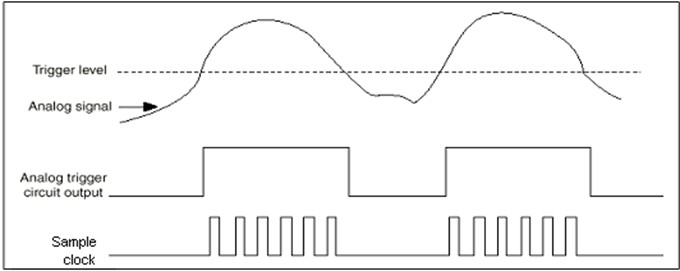
Figure 17: Analog Pause Trigger