NI PXI Modular Instrument Design Advantages
Contents
- Overview
- Instruments for Any Application
- Performance and Quality of Measurement
- Choice of Flexible Software Development Environments
- Measurement and Control Services
- Modular Instrument Production Unit Verification
- Other NI PXI Design Advantages
Overview
With software-defined modular instruments, engineers can design and implement flexible test systems that can be repurposed quickly. Of the more than 1,500 PXI products on the market, more than 600 were designed by National Instruments. With this proven history, PXI instrumentation designed by NI offers several advantages. This paper examines these advantages: instruments for any application, performance and quality of measurement, choice of software architectures, and production unit verification.
Instruments for Any Application
NI offers more than 600 modular instruments based on PXI and PXI Express technology. These instruments range from DC to 26.5 GHz, including the industry’s highest resolution digitizer with 24 bits of resolution and the industry’s fastest, most accurate 7½-digit digital multimeter (DMM).
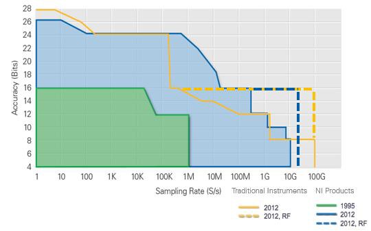
Figure 1. NI modular instruments span from the industry’s highest resolution to the industry’s highest accuracy.
NI is continually pushing the boundaries of performance with its PXI modular instruments, all in a more efficient 3U space. With the addition of the NI PXIe-5668 vector signal analyzer (VSA), NI offers best-in-class RF accuracy and test speed on the PXI platform, exceeding that of industry-standard benchtop instruments. Another example of leading measurement technology is the NI PXIe-5186 digitizer, codeveloped by National Instruments and Tektronix™, the world’s leading oscilloscope manufacturer. It is the highest performing PXI digitizer on the market, with 5 GHz bandwidth and up to 12.5 GS/s sampling rate.
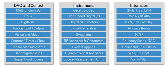
Table 1. The NI modular instrument portfolio features products for every application.
NI not only offers a vast modular instrumentation portfolio but also enables the use of field-programmable gate arrays (FPGAs) with the PXI platform. FPGAs present a powerful solution for applications that require the ability to manage large data sets while still needing flexibility and customization. NI FlexRIO provides flexible, customizable I/O for the NI LabVIEW FPGA Module to help you create high-performance, reconfigurable instruments. LabVIEW FPGA extends the LabVIEW graphical development platform to target FPGAs. LabVIEW is well suited for FPGA programming because it clearly represents parallelism and data flow, so users who are both experienced and inexperienced in traditional FPGA design can productively apply the power of reconfigurable hardware. With an open, customizable signal front end, you can meet the exact requirements of a test or embedded system.
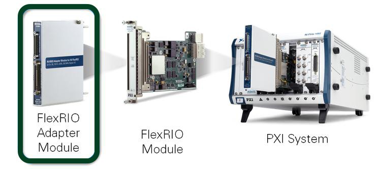
Figure 2. Take advantage of NI FlexRIO to help target your applications to FPGAs and expand system capabilities.
The NI Vector Signal Transceiver (VST) is another example of NI hardware enabled by the LabVIEW RIO architecture. VSTs combine a vector signal analyzer and vector signal generator with a user-programmable FPGA for real-time signal processing and control. By combining standard instrumentation with a user-programmable FPGA, you can now take advantage of a software-designed PXI instrument and use LabVIEW to tailor the FPGA-based hardware to a specific application. Software-designed instrumentation provides the highest level of flexibility, performance, and future-proofing to ensure you can adapt your existing I/O while preserving your software investment as system requirements change.
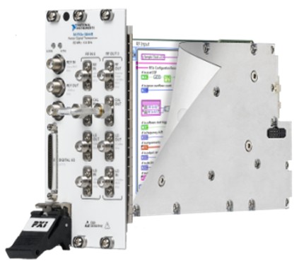
Figure 3. Meet changing system requirements using LabVIEW to tailor the FPGA-based hardware to a specific application.
Performance and Quality of Measurement
NI incorporates several proprietary and patented technologies in its modular instruments to ensure that they function at the highest level and return reliable measurements for today’s most demanding applications. These technologies include the following:
- The Synchronization and Memory Core (SMC)
- NI-TClk timing and synchronization technology for modular instruments
- NI-STC3 timing and synchronization technology for multifunction data acquisition
- NI-MCal calibration algorithm for data acquisition
Synchronization and Memory Core (SMC)
Today’s latest electronic designs are characterized by their converging functionality and the increase in seemingly interwoven analog and digital technology. Designing, prototyping, and testing these systems that involve a mix of video, audio, and data, such as latest-generation wireless handsets and set-top boxes, requires tightly integrated digital and analog acquisition and generation hardware matched in baseband sampling rate, distortion, and timing characteristics. Analog and digital instrumentation can no longer be stand-alone systems with disparate timing engines and mismatched analog performance. Furthermore, with the manufacture of such devices running around the clock in many locations around the world, the need for stability and consistency of performance specifications over a wide temperature range is compulsory for reliable, high-throughput functional test.
NI designed the Synchronization and Memory Core (SMC) as the common architecture for a suite of high-speed modular instruments that answer the challenge of testing converged devices. The SMC features critical to integrated mixed-signal prototyping and test systems are
- Flexible input and output data transfer cores
- High-speed deep onboard memory scalable up to 512 MB per channel
- Precise timing and synchronization engine
Central to the SMC architecture is an FPGA controller, the DataStream FPGA (DSF), which is the “CPU” of the instrument. It processes all instructions, listens to triggers and locks, routes signals externally, and manages waveform traffic between the instrument and the host computer.
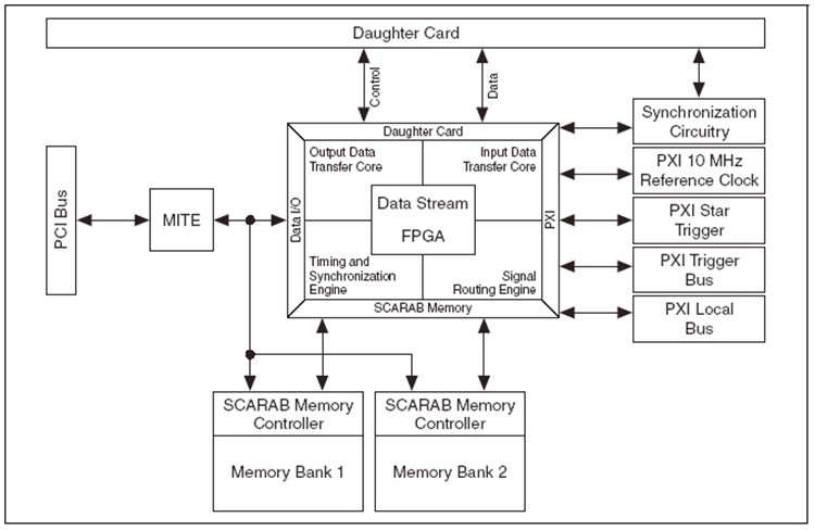
Figure 4. SMC Architecture
Timing and Synchronization With National Instruments T-Clock Technology for Modular Instruments
Many test and measurement applications call for the timing and synchronization of multiple instruments because of the limited number of stimulus/response channels on a single instrument and/or the need for mixed-signal stimulus/response channels. For example, an oscilloscope may have up to four channels and a signal generator up to two channels. Applications ranging from mixed-signal test in the electronic industry to laser spectroscopy in the sciences require timing and synchronization for higher count channels and/or the need to correlate digital input and output channels with analog input and output channels.
The PXI platform, specifically chassis, features integrated timing and synchronization capabilities, enabling coherence among PXI modules. Even so, distributing clocks and triggers to achieve high-speed synchronized devices has its challenges. The latencies and timing uncertainties in orchestrating multiple-measurement devices add up to a significant barrier to synchronization, especially for high-speed measurement systems. These issues, often overlooked during the initial system design, limit the speed and accuracy of synchronized systems. Two main issues that arise in the distribution of clocks and triggers are skew and jitter.
NI has developed a patent-pending method for synchronization whereby another signal-clock domain is used to enable sample clock alignment and trigger distribution and reception. The objectives of NI T-Clock (NI-TClk) technology are twofold:
- It aligns the sample clocks that may not be necessarily aligned initially despite being phase locked to the 10 MHz reference clock.
- It enables the accurate triggering of synchronized devices.
PXI Express chassis are designed to achieve slot-to-slot skew of 100 ps maximum, which is satisfactory for most applications. With NI-TClk technology, you can lower this to less than 10 ps, enabling tighter multichannel phase coherence for high-speed modular instruments.
NI-TClk synchronization is flexible and wide ranging; it can address the following use cases:
- Extension of synchronization from a single PXI chassis to several PXI chassis to address high-channel systems using NI PXI-665x and NI PXIe-667x system timing and control modules
- Homogeneous and heterogeneous synchronization—devices running at the same or different sample rates, using internal or external sample clocks
The purpose of NI-TClk synchronization is to have devices respond to triggers at the same time. The “same time” means on the same sample period with very tight alignment of the sample clocks. NI-TClk synchronization is accomplished by having each device generate a trigger clock that is derived from the sample clock. Triggers are synchronized to a TClk pulse. A device that receives a trigger from an external source, or generates it internally, then sends the signal to all devices, including itself, on a falling edge of TClk. All devices react to the trigger on the following rising edge of TClk.
To read more about NI-TClk and how it works, refer to the National Instruments T-Clock Technology for Timing and Synchronization of Modular Instruments paper.
NI-STC3 Timing and Synchronization Technology for Multifunction Data Acquisition
NI-STC3 timing and synchronization technology delivers a new level of performance to NI X Series multifunction DAQ devices. This technology is the driver behind the advanced digital, timing, triggering, synchronization, counter/timer, and bus-mastering features.
A retriggerable task is a measurement task that executes a specified operation each time a specific trigger event occurs. Previous generations of synchronization and timing technology were only able to retrigger counter operations, which could provide retriggerable sample clocks for other tasks but created fairly complex code. NI-STC3 technology now equips all acquisition and generation tasks with inherent retriggerable capabilities.
NI-STC3 technology also provides a faster 100 MHz timebase, replacing the 80 MHz timebase used by previous devices for many counter applications. The 100 MHz timebase is also used to generate analog and digital sampling or update rates, compared to a 20 MHz timebase used in prior devices. For generating arbitrary sampling rates, the generated clock rate can now be significantly closer to the user-requested rate because of this 5X speed improvement. In addition, the faster timebase and improved device front end reduce the time between triggering and the first sample clock edge, which improves the responsiveness of the device to triggers.
Buffered counter input functionality, using NI-STC3 technology, has improved on its predecessors’ capabilities in the areas of buffered period and frequency measurements. Although you can continue selecting implicit as the timing type, you can now select sample clock as well. When using a sample clock as the timing type, you make buffered frequency and period measurements by counting both an internal timebase (counted by embedded counter) as well as the unknown signal of interest up until the rising edge of the sample clock. However, the sample clock is a signal that you must specify and create. You then divide the ideal frequency of the internal timebase by its count to find the effective frequency up to the next sample clock edge.
NI-STC3 technology also offers several features for the digital I/O and programmable function input (PFI) lines on X Series devices. These include programmable power-up states, watchdog timers, event detection, and new PFI filtering.
With NI-STC3 technology, you can now accomplish more advanced analog, digital, and counter operations than ever before. In addition, applications that previously required additional onboard resources or were difficult to program can now execute independently and with less NI-DAQmx code.
Calibration Algorithm for Data Acquisition With NI-MCal
NI-MCal is a software-based calibration algorithm that generates a third-order polynomial to correct for the three sources of voltage measurement error: offset, gain, and nonlinearity. Using software-based measurement corrections, NI-MCal can optimize every selectable range with a unique correction polynomial that hardware-based calibration cannot accommodate.
The NI-MCal algorithm executes when a self-calibration function is called from software such as LabVIEW. On a typical modern PC, NI-MCal takes less than 10 seconds to characterize nonlinearity, gain, and offset and to save the correction polynomials to the onboard EEPROM. Subsequent measurements are scaled automatically by the device driver software before being returned to you through application software. Unlike other self-calibration schemes, NI-MCal has the unique ability to return calibrated data from every channel in a scan, even if the channels are at different input ranges. This is because NI-MCal determines, saves, and applies correction polynomials for every input range on the device. Other self-calibration mechanisms use hardware components for data correction, and cannot dynamically load correction functions fast enough to provide accuracy when multiple input ranges are used in a single scan. Instead, NI-MCal uses software for data correction, which can easily load and apply channel-specific correction functions even while scanning at maximum device rates.
NI-MCal performs unlike other self-calibration techniques by correcting for nonlinearity error in addition to applying channel-specific data correction functions for all channels in a scan sequence. By eliminating the limitations of hardware components traditionally used for device error correction and using the power and speed of software and PC processing, NI-MCal raises the bar for measurement accuracy and redefines device self-calibration.
To read more about NI-MCal and how it works, refer to the NI-MCal section of NI Data Acquisition: The Accuracy and Performance Difference.
Choice of Flexible Software Development Environments
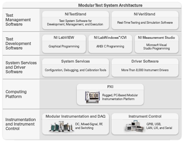
Figure 5. Reduce development time with LabVIEW graphical programming.
PXI modular instruments from NI are compatible with Windows OSs, real-time OSs for applications that require deterministic operation, and common Linux distributions. This provides the flexibility you need to design your modular instrumentation system.
Windows OSs
The development and operation of a Windows-based PXI system is no different from that of a standard Windows-based PC. Therefore, you do not have to rewrite existing application software or learn new programming techniques when moving between PC-based and PXI-based systems.
If you select PXI, you can reduce your development time and quickly automate your instruments using NI LabVIEW, an intuitive graphical programming language that is an industry standard for test, or NI LabWindows™/CVI for C development. You can also use other programming languages such as Visual Studio .NET, Visual Basic, and C/C++.
In addition, PXI controllers can run applications developed with test management software such as NI TestStand. For more information on developing test architectures for PXI, read this white paper on developing a modular software architecture.
Real-Time OSs
As an alternative to Windows-based systems, you can use a real-time software architecture for time-critical applications requiring deterministic loop rates and headless operation (no keyboard, mouse, or monitor). Real-time OSs help you prioritize tasks so the most critical task always takes control of the processor, which reduces jitter. You can simplify the development of real-time systems by using real-time versions of industry-standard development environments such as the LabVIEW Real-Time and LabWindows/CVI Real-Time modules. Engineers building dynamic or hardware-in-the-loop test PXI systems can use real-time testing software such as NI VeriStand to further reduce development time. Visit the real-time measurements portal to learn more about deterministic test.
Linux OSs
NI also supports many hardware devices, including modular instruments in the PXI platform, on common distributions of Linux. Visit the National Instruments Linux Portal for further information on Linux support. For further information on how to install, visit Downloading and Installing NI Driver Software on Linux Desktop.
Measurement and Control Services
NI modular instruments feature robust software interfaces such as NI Measurement & Automation Explorer (MAX), NI-DAQmx, Virtual Instrument Software Architecture (VISA), LabVIEW Plug & Play drivers, and Interchangeable Virtual Instrument (IVI) drivers. This measurement and control services software provides modular hardware interfaces for configuring and programming your tests. Most NI modular instruments come with soft front panels (SFPs), which you can use to quickly troubleshoot or debug your instrument. These measurement and control services software packages help you avoid developing test programs that are permanently tied to specific hardware and channels in your test system, thus increasing the ease of code reuse. Take a closer look at each of these components.
Configuration Manager
A configuration manager, such as MAX, presents a unified system view of measurement hardware. With MAX, you can define channel names to organize signals or specify scaling functions to convert digitized signals to measurement quantities. The key benefit of the configuration manager is the integration with the application development environments (ADEs). This integration gives you the ability to integrate multiple measurements easily into a single application without tedious programming. Without these configuration tools, you must spend time configuring these measurement functions programmatically.
Instrument Connectivity
Integrating existing traditional instruments into the test software framework should exploit technologies, such as Plug & Play instrument drivers and IVI, to facilitate the communication with these instruments and their interchangeability. A Plug & Play instrument driver is a set of functions, or VIs in the case of LabVIEW, that control a programmable instrument. Instrument drivers help you get started using your instrument from your computer and save you development time and cost because you do not need to learn the programming protocol for each instrument. With open-source, well-documented instrument drivers, you can customize your operation for better performance.
IVI implements a driver framework that facilitates instrument interchangeability. An IVI driver uses a general API for each kind of instrument and separately implements the driver to communicate with particular instruments. By separating the application programming interface (API) from the particular driver implementation of each instrument, you can design a system using a particular IVI-compliant oscilloscope; once the system is deployed, you can change the brand and model of the instrument without having to rewrite the test application.
Programming Tools
Drivers can go one step beyond providing an easy-to-use API by adding tools to facilitate development and save you time. I/O assistants are interactive tools for rapidly creating a measurement or stimulus application. An example of an I/O assistant is the DAQ Assistant, which is part of the NI-DAQmx driver. The DAQ Assistant presents a panel to you for configuring common data acquisition parameters without programming. The combination of easy-to-use assistants and powerful programming environments is necessary to offer both rapid development and the capabilities to meet a breadth of application requirements.
Example Programs
In addition to the measurement and control services software discussed above, all NI modular instruments are shipped with several example programs. For example, NI-DCPower, an IVI-compliant instrument driver for NI precision DC sources, includes example programs that demonstrate concepts ranging from simple configuration to advanced sweeping and monitoring.
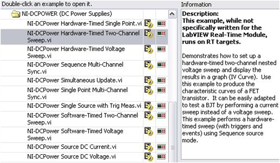
Figure 6. Example Programs Included With NI-DCPower
Modular Instrument Production Unit Verification
After an NI PXI modular instrument design has moved to full production, NI ensures each production unit is evaluated to meet its specification. Each modular instrument produced endures hours of rigorous testing to ensure that it reliably operates once deployed in its intended application. These tests include automated optical inspection (AOI), in-circuit test (ICT), initial functional test (IFT), environmental stress screening (ESS), and functional verification test (FVT).
The first inspection performed, AOI, compares in memory a sketch of a known good product to each new product manufactured for part orientation errors or missing parts. ICT checks for shorts, opens, or backward components by evaluating the resistance between all of the board’s test points. IFT ensures the basic functionality of the product in that it checks for a successful power-up sequence. ESS comprises a thermal conditioning test (TCT) and a highly accelerated stress screening (HASS), during which the production boards are brought to a certain temperature and their responses are monitored, both nonstimulated and under stimulation. These “burns” can last from several hours to several days. Finally, production units undergo an FVT, during which all modular instruments are calibrated to ensure adherence to specification. For some instruments, their test FVT stations are calibrated on a weekly basis to ensure accuracy.
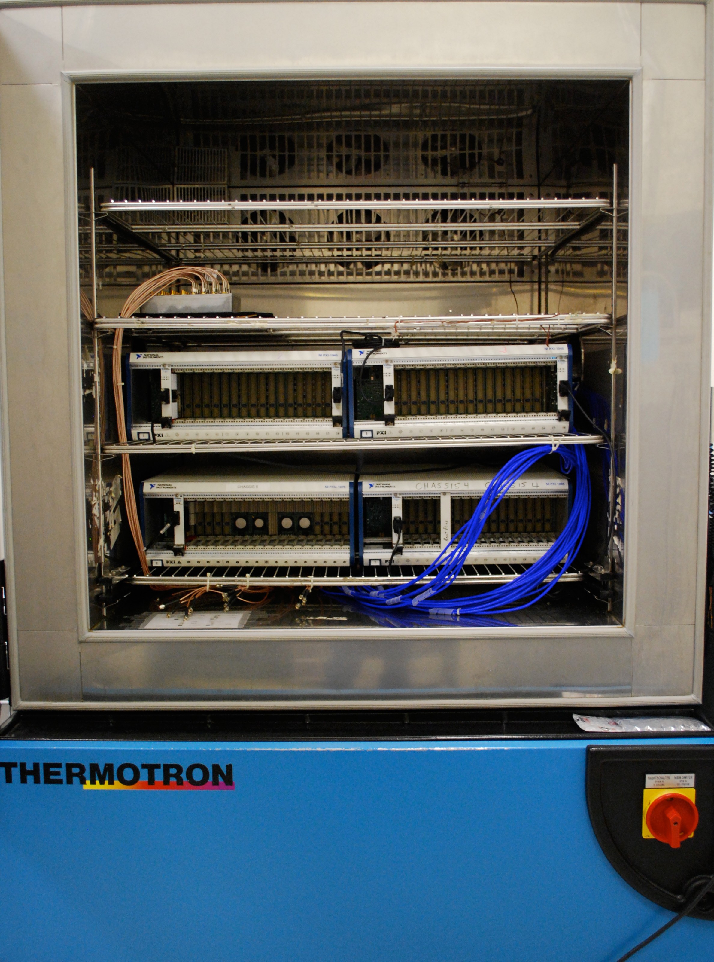
Figure 7. HASS Temperature Chamber at National Instruments
Other NI PXI Design Advantages
NI PXI Platform Design Advantages
The mark LabWindows is used under a license from Microsoft Corporation. Windows is a registered trademark of Microsoft Corporation in the United States and other countries. Tektronix is a trademark of Tektronix, Inc.