ni.com checkout is currently experiencing issues.
Support teams are actively working on the resolution.
ni.com checkout is currently experiencing issues.
Support teams are actively working on the resolution.
CANopen is a high-level communication protocol and device profile specification that is based on the CAN (Controller Area Network) protocol. The protocol was developed for embedded networking applications, such as in-vehicle networks. The CANopen umbrella covers a network programming framework, device descriptions, interface definitions and application profiles. CANopen provides a protocol which standardizes communication between devices and applications from different manufacturers. It has been used in a wide range of industries, with highlights in automation and motion applications.
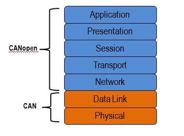
In terms of the OSI communication systems model, CAN covers the first two levels: the physical layer and the data link layer. The physical layer defines the lines used, voltages, high-speed nature, etc. The data link layer includes the fact that CAN is a frame-based (messages) protocol. CANopen covers the top five layers: network (addressing, routing), transport (end-to-end reliability), session (synchronization), presentation (data encoded in standard way, data representation) and application. The application layer describes how to configure, transfer and synchronize CANopen devices. The concepts of the application layer, covered in specification CiA DS 301, are covered in this document. The intention is to give users a brief overview of the concepts of CANopen.
The following section explains the basic concepts related to the CANopen protocol application layer. This document is intended as a basic overview only, and users are encouraged to review the CiA DS 301 specification for more information.
One of the central themes of CANopen is the object dictionary (OD), which is essentially a table that stores configuration and process data. It is a requirement for all CANopen devices to implement an object dictionary. The CANopen standard defines a 16-bit bit index and an 8-bit sub-index. That is, it is permissible to have up to 65536 indices and up to 256 subentries at each index. The standard defines that certain addresses and address ranges must contain specific parameters. For example, the standard defines that index 1008h, sub-index 00h, must contain the device name. As such, any CANopen master can read this index from a network of CANopen slaves in order to uniquely identify each slave by name. Some object dictionary indices, such as the device type (1000h) are mandatory, and others, such as the manufacturer software version (100Ah) are optional. The collection of mandatory indices represents the minimum object dictionary, which is required to brand a device CANopen compliant.
The object dictionary is the method by which a CANopen device can be communicated with. For example, one could write a true to the index in the manufacturer-specific section of the object dictionary (2000h-5FFFh), which the device could interpret as an enable signal for acquiring data from a voltage input. Conversely, the master may also want to read information from the object dictionary to get the acquired data, or to find out how to device is currently configured. The two communication mechanisms for accessing the object dictionary are Service Data Objects (SDOs) and Process Data Objects (PDOs), which will be explained later in this document.
The basic data types included in the object dictionary are: Boolean, void (placeholder), unsigned integer, signed integer, floating point and character. More complex data types, such as strings, date and time can be constructed from the basic data types. These data types can be used to define custom data types specific to CANopen, such as the PDO/SDO Parameter Record and the PDO mapping parameter. The user is encouraged to review the CANopen specification for more details on the components of complex and custom data types.
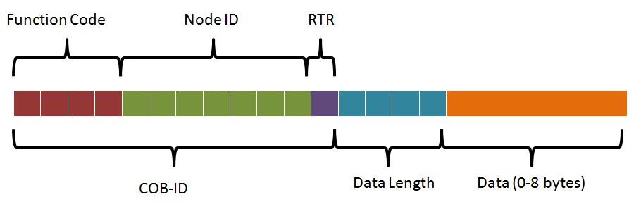
The message format for a CANopen frame is based on the CAN frame format. In the CAN protocol, the data is transferred in frames consisting of an 11-bit or 29-bit CAN-ID, control bits such as the remote transfer bit (RTR), start bit and 4-bit data length field, and 0 to 8 bytes of data. The COB-ID, commonly referred to in CANopen, consists of the CAN-ID and the control bits. In CANopen, the 11-bit CAN ID is split into two parts: a 4-bit function code and a 7-bit CANopen node ID. The 7-bit size limitation restricts the amount of devices on a CANopen network to 127 nodes.
All COB-ID's must be unique to prevent conflicts on the bus. In SDO communication, there should always be only one node that needs to access the individual object dictionary indices of the slave nodes.
The CANopen protocol also specifies that each node on the network must implement a server that handles read/write requests to its object dictionary. This allows for a CANopen master to act as a client to that server. The mechanism for direct access (read/write) to the server’s object dictionary is the Service Data Object (SDO). The node whose object dictionary is accessed is referred to as the SDO server, and the node grabbing the data is referred to as the SDO client. The transfer is always started by the SDO client.
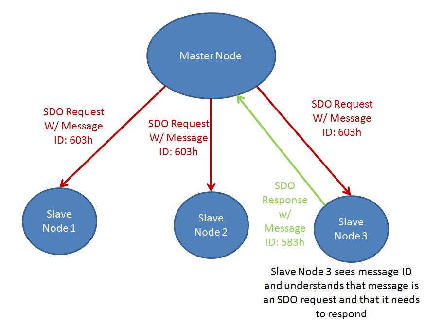
Typically, the master CANopen node will send a request to the network, and the node of interest will respond with the data requested. CANopen uses reserved message IDs to facilitate this communication. When the SDO client wants to request information from the server, it sends an SDO request using a CAN-ID of 600h + Node ID. The server will then respond using a CAN-ID of 580h + Node ID. The Node ID specifies which slave node the message is coming from. For the example illustrated below, the master node (the SDO client) sends a message out to the network with a CAN-ID of 603h. Although all nodes see this message, all nodes but the targeted node ignore it because the message is not intended for them. The targeted node understands that the message with ID 603h means that the message is intended for that node, which is an SDO request. The data field of the message will specify the index and sub-index of the object which the master would like to access data. The targeted node then responds with message ID 583h. The data field of the response message will contain the data requested.
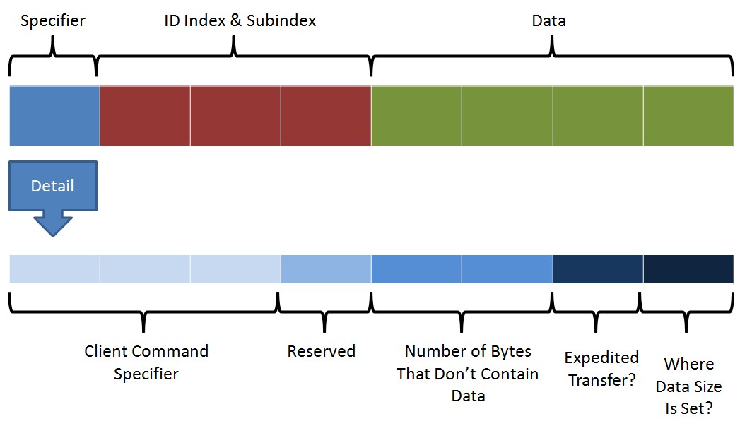
In addition to having a specific CAN-ID, the data section of the CANopen frame also follows a specific format for SDO. The data section of the CAN frame is split into three parts: one byte for the specifier, three bytes for the node index and subindex, and four bytes for the actual data in the transfer. The specifier byte is broken out in the diagram shown above. The three bits of the specifier byte are referred to as the client command specifier (ccs), which indicates what type of message is being transferred (i.e. read, write, and abort). The fourth bit is reserved. The fifth and sixth bits indicate the number of bytes in the data part of the message that do not contain actual data. The seventh bit indicates whether the transfer is an expedited transfer or a segmented transfer. The final bit indicates whether the amount of data is specified in bit five/six or whether it is specified in the data part of the message.
A segmented transfer is selected when all the data that needs to be transferred does not fit into a single message, and therefore the data must be transferred using multiple messages or "segments". On the contrary, an expedited transfer is where all data is sent as a single message. In the initialization phase (see NMT section), SDOs can transfer up to four bytes of data. Optionally, an SDO transfer can also occur in a series of blocks. Each block consists of up to 127 segments. A block transfer is faster than a segmented transfer for large data sets.
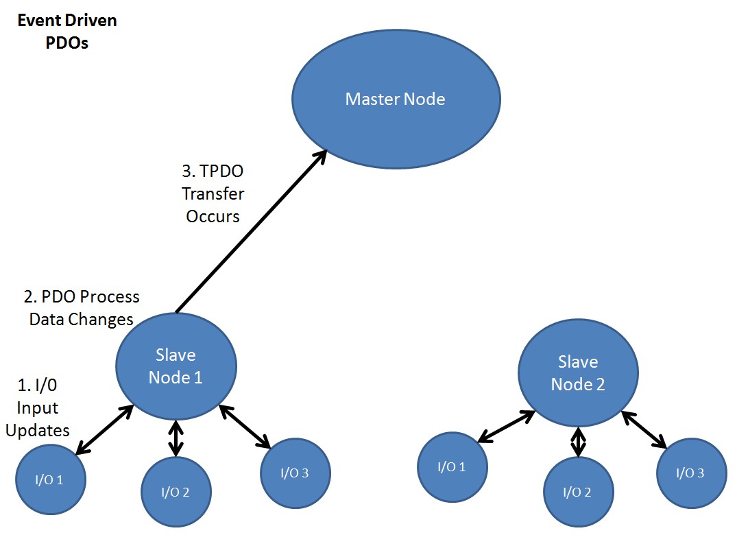
Process data represents data that can be changing in time, such as the inputs (i.e. sensors) and outputs (i.e. motor drives) of the node controller. Process data is also stored in the object dictionary. However, since SDO communication only allows access to one object dictionary index at a time, there can be a lot of overhead for accessing continually changing data. In addition, the CANopen protocol has the requirement that a node must be able to send its own data, without needing to be polled by the CANopen master. Thus, a different method is used to transfer process data, using a communication method called Process Data Objects (PDOs).
There are two types of PDOs: transfer PDOs (TPDOs) and receive PDOs (RPDOs). A TPDO is the data coming from the node (produced) and a RPDO is the data coming to the node (consumed). In addition, there are two types of parameters for a PDO: the configuration parameters and the mapping parameters. The section of the object dictionary reserved for PDO configuration and mapping information are indices 1400h-1BFFh.
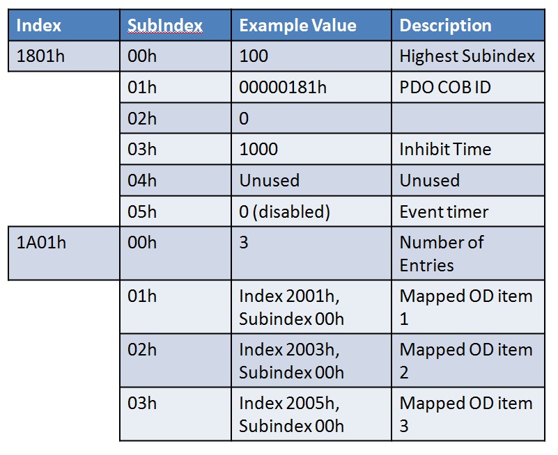
The configuration parameters specify the COB-ID, the transmission type, inhibit time (TPDO only) and the event timer, which are explained in this section. There are different methods through which a PDO transfer can be initiated. These methods include event driven, time driven, individual polling and synchronized polling. The type of transmission is specified in the configuration parameters of the PDO. In event driven transmission, the PDO transfer is initiated when the process data in it changes. In time driven transmission, the PDO transfer occurs at a fixed time interval. In individual polling, the PDO transfer is initiated using a mechanism called remote request, which is not commonly used. In synchronized polling, the PDO transfer is initiated using a SYNC signal. The sync signal is frequently used as a global timer. For example, if the CANopen master sends out a SYNC message, multiple nodes may be configured to see and respond to that SYNC. In this way, the master is able to get a "snapshot" of multiple process objects at the same time.
The mapping parameters specify which object dictionary values are sent by a single PDO message. For example, a single PDO message may contain data from object index 2001h, 2003h and 2005h.
Network management services include the ability to change the state of a slave between initializing, pre-operational, operational and stopped. The NMT protocol allows for the CANopen network to control the communication state of individual nodes. The pre-operational state is mainly used to for the configuration of CANopen devices. As such, PDO communication is not permitted in the pre-operational state. PDO communication becomes possible in the operational state. In the stopped state, a node can only do node guarding or heartbeats, but cannot receive or transmit messages. Certain types of CANopen communication are allowed in different states. For example, SDOs are allowed in the preoperational state, but PDOs are not. This is because SDOs are often used to initialize object dictionary parameters, whereas PDOs are often used to transfer continually updating data.
The CANopen specification requires that nodes must use some method to check whether a node is "alive" or not. The two methods available are: node guarding and heartbeats, with the latter being the preferred method.
In the heartbeat protocol, a CANopen node periodically sends out a heartbeat message which lets the CANopen master or the heartbeat consumer, know that the node is still alive. If a heartbeat message does not arrive within a certain period of time, the master can take a specific action. Such an action might be to reset the node or to report an error to an operator. The heartbeat message is identified by a CAN-ID of 0x700 + the node ID, where the first data byte is equal to 1110.
In the node guarding protocol, the CANopen master polls the slave nodes for their current state information. If the node does not respond in a specific period of time, the master assumes the node is dead and will take an action.
The heartbeat protocol is the preferred method because it has less overhead than node guarding.
Each node in a CANopen network is assigned a single emergency (EMCY) message that communicates the node's status. Note that the heartbeats and node guarding protocol are intended to be used to convey communication failures, whereas emergency messages are used to convey errors within the node (i.e. sensor failure). An EMCY message is identified by a COB-ID of 80h + Node ID. The data portion of an EMCY message contains information about the error that occurred.
National Instruments offers CANopen master interfaces for CompactRIO, PXI, and PCI form factors. Each interface is supported by the Industrial Communications for CANopen driver, which features support for SDOs, PDOs, NMT, heartbeats, node guarding and synchronization. The driver also features a Batch SDO editor, which allows a user to easily configure the nodes on the CANopen network. The Batch SDO Editor has support for EDS file integration and LSS services support for slave node configuration.
The NI 9881 is a 1-port, high-speed CANopen C Series module interface for developing CANopen applications in NI LabVIEW software on NI CompactRIO hardware. The NI-9881 is externally powered and can attain transfer rates of up to 1Mbit/s. The CANopen port is accessible from the CompactRIO Real-Time controller. The 9881 module requires the NI cRIO-911x chassis and the LabVIEW FPGA Module.
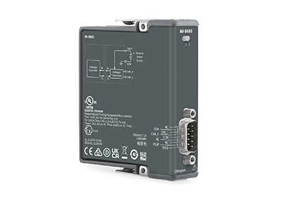
Learn more about the C Series CANopen Interface Module
The NI PCI-8531 and NI PXI-8531 are both 1-Port CANopen Interfaces for the PCI and PXI platforms, respectively. They feature transfer rates of up to 1 Mbit/s, and leverage the Industrial Communication for CANopen Driver.
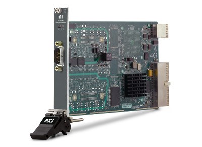
Learn more about the CANopen Interface Device
Learn more about the PXI CANopen Interface Device
Related Links
National Instruments CANopen Interfaces Home Page
KnowledgeBase 5W8COLVO: Summary of CANopen Software Availability and Compatibility with National Instruments Products